Extending the service life of an industrial cable extrusion line beyond a decade requires shifting from reactive repairs to structured preventative maintenance. Without regular inspection, thermal drift, mechanical misalignment, and mechanical wear degrade process stability, leading to insulation eccentricity, surface flaws, and unscheduled line downtime.
Achieving long-term equipment reliability depends on systematic control over mechanical clearances, thermal stability across heating zones, oil cleanliness in drive assemblies, and crosshead alignment. This guide details a complete shift-by-shift preventative maintenance schedule, diagnostic procedures for core wear points, defect-to-maintenance root-cause mapping, and total cost of ownership (TCO) benchmarks to help engineering and plant management teams protect capital investments.

The 10-Year Lifecycle: Why Preventive Maintenance Dictates Cable Extrusion ROI
In cable manufacturing, an unmaintained extrusion line typically exhibits severe mechanical and thermal degradation within three to five years of continuous operation. As screw flights and barrel linings wear down, the extruder loses plasticizing efficiency, requiring operators to increase screw speeds to hit target output rates. This compensatory behavior accelerates mechanical shear, introduces melt temperature spikes, and shortens the operational lifespan of the entire drive system.
Equipment Lifecycle: Preventive vs. Reactive Regimes
| Operational Parameter | Reactive Strategy (Run-to-Fail) | Preventive SOP (10+ Years) |
| Core Barrel/Screw Life | 3–5 Years | 8–12+ Years |
| Insulation Centricity | High Variance / High Scrap Rate | Stable (less than 3% Variation) |
| Gearbox Oil Changes | Only Upon Failure / Noise | Scheduled by Viscosity and Runtime |
| Thermal Zone Accuracy | Drift of ±5°C to 10°C | Calibrated ±1°C |
| Unplanned Downtime | 120–250+ Hours / Year | Less than 20 Hours / Year |
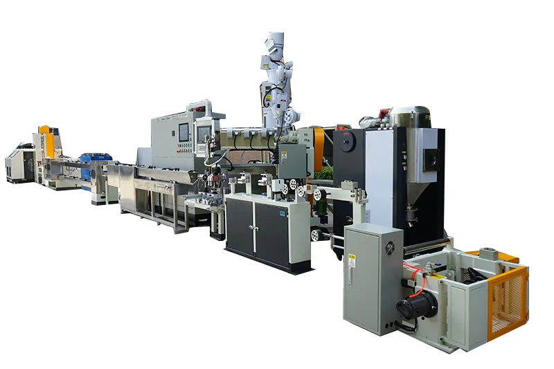
When preventative protocols are strictly enforced, the total cost of ownership decreases significantly. Minimizing thermal and mechanical stress preserves the initial factory alignment of the extruder barrel, crosshead, cooling trough, and capstan, allowing heavy-duty machinery like a heavy-duty cable extrusion line to maintain strict concentricity standards across more than a decade of active production.
Core Subsystems Vulnerable to Accelerated Wear in Cable Extrusion
Cable extrusion involves sustained mechanical shear, high head pressure, and cyclic thermal expansion. Maintenance teams must monitor four critical subsystems where wear directly degrades finished product quality.
Screw and Barrel Assembly: Abrasion, Galling, and Clearances
The interaction between the rotating screw and the inner barrel wall is subject to constant friction, compounded by abrasive polymer additives such as flame retardants, mineral fillers (e.g., calcium carbonate), and color masterbatches. Over time, flight-to-barrel clearances expand beyond engineering tolerances. This clearance expansion causes melt backflow, reduces pumping efficiency, and generates localized shear scorching that contaminates finished cable jackets with degraded carbon particles.
Drive Train & Gearbox: Vibration, Thermal Load, and Lubrication Breakdown
The main drive transmission transfers high torque under continuous axial thrust loads countered by specialized thrust bearings. Gear oil degrades through shear stress, oxidation, and particulate contamination from metallic wear. Operating with degraded gear oil or improper oil viscosity accelerates pitting on helical gear teeth, destabilizes output RPM, and causes output surging in the melt stream.
Heating & Cooling Zones: Thermocouple Drift and Water Jacket Clogging
Extruder temperature stability relies on closed-loop feedback between electrical heating bands and barrel cooling channels. Two failure modes dominate this subsystem:
Thermocouple Drift: Oxidation and mechanical loosening distort temperature readings, causing overheating even when the control panel shows nominal levels.
Jacket Scale Buildup: Mineral scaling inside liquid cooling channels restricts coolant flow, causing cooling zone delay and localized thermal runaway during high-speed runs.
Crosshead & Die Assembly: Centering Stability and Melt Pressure Integrity
The crosshead operates under continuous hydrostatic pressure. Repeated assembly, disassembly, and thermal cycling can deform centering bolts and seating surfaces. Worn crosshead guide surfaces or improperly torqued die retainers allow microscopic shifts during production, resulting in wall thickness variance and insulation eccentricity along the cable length.
The Complete Cable Extrusion Line Maintenance Checklist
Implementing standardized maintenance procedures ensures consistent processing conditions across shifts. The following procedures outline actionable checks categorized by operating interval.
Daily Pre-Shift and Post-Shift Inspection Protocol
Melt Pressure Transducer: Verify that zero-point calibration is set correctly at working temperature before starting the drive motor.
Barrel Feed Throat Cooling: Confirm water flow and temperature at the feed zone throat to prevent early pellet softening and bridging.
Lubrication Levels: Check sight glasses on the main gearbox and thrust bearing assembly for correct oil levels and absence of milky emulsification.
Haul-off and Capstan Belts: Inspect belt tension, belt surfaces, and grip grooves for polymer residue, chips, or mechanical wear.
Heater Zone Status: Confirm all heating zones reach and stabilize at setpoint values without tripping breaker alarms.
Weekly Mechanical & Fluid Checks
Breaker Plate & Screen Pack Seats: Inspect for surface galling, burrs, or polymer bypass leakage around seal rings.
Cooling Trough Alignment & Seals: Check water inlet filters, spray nozzles, and end seals for blockages or leakage along the trough line.
Air Wipers & Blow-off Units: Clean nozzles to ensure moisture is completely removed from the cable surface prior to inline spark testing and diameter gauging.
Drive Belt Deflection: Measure deflection tension on auxiliary motor belts, capstan drives, and take-up traversers.
Monthly Calibration & Electrical Safety Verification
Thermocouple Calibration: Test temperature feedback accuracy against a calibrated reference probe across all barrel and crosshead heating zones.
Heating Band Clamping Tightness: Retighten barrel heater band clamps; thermal expansion cycles loosen band contact, leading to localized burnout.
Emergency Stop & Interlock Circuits: Function-test all emergency stop buttons, interlocked safety covers, motor cut-off switches, and line-stop alarms.
Take-up / Pay-off Tension Arms: Verify dancer potentiometer responsiveness and pneumatic cylinder seals for smooth tension control.
Annual Major Overhaul and Precision Alignment Audit
Gearbox Oil Replacement: Drain, flush, and refill the extruder reduction gearbox using manufacturer-approved industrial synthetic gear oil.
Laser Axis Alignment: Check co-axial alignment between the motor output shaft, reduction gearbox, extruder barrel, crosshead, and water trough track.
Screw Runout & Profile Measurement: Pull the extruder screw to measure flight wear, verify straightness runout, and inspect the barrel inner diameter across its length.
Electrical Cabinet De-dusting & Terminal Retorquing: Clean dust filters, verify ventilation fans, and retorque high-voltage terminals to eliminate micro-arcing from factory vibration.
How to Inspect and Measure Screw & Barrel Wear Accurately
Maintaining correct radial clearance between the screw flights and the barrel liner is critical for process stability. Once clearance widens beyond acceptable limits, output consistency and melt quality decline.
Measuring Radial Clearance with Feeler Gauges and Inside Micrometers
Tooling Setup: Clean the screw and barrel thoroughly while warm using brass tools and copper gauze. Never use hardened steel scrapers that can score bimetallic surfaces.
Radial Clearance Check (In-Situ): For accessible zones, slide calibrated feeler gauge blades between the flight crest and the barrel top dead-center.
Comprehensive Bore Micrometer Inspection (Screw Extracted):
Mount a calibrated three-point internal bore micrometer on an extension rod.
Take bore diameter measurements at three positions (horizontal, vertical, 45-degree angle) across the feed zone, compression zone, and metering zone.
Measure screw flight outside diameters with a blade micrometer at identical zone intervals.
Calculate radial clearance:
$$\text{Clearance} = \frac{\text{Barrel Inside Diameter} – \text{Screw Flight Outer Diameter}}{2}$$
Critical Wear Thresholds: When to Resurface vs. Replace
| Clearance Condition | Wear Ratio Relative to Nominal Clearance | Operational Effect | Recommended Action |
| Nominal Operating State | 1.0x – 1.5x | Optimal melt output, linear pressure build, low backflow. | Maintain standard PM inspection schedule. |
| Moderate Clearance Expansion | 1.6x – 2.2x | Slight output drop (5–10%), mild melt temperature instability. | Adjust process parameters; order replacement screw/barrel. |
| Severe Clearance Degradation | Greater than 2.5x | Severe output drop, polymer surging, degraded resin flecks. | Immediate overhaul; resurface flight tips or replace barrel liner. |
When wear extends deeply into the parent metal beneath the bimetallic protective layer, resurfacing is no longer cost-effective, and replacing the component is necessary to prevent complete processing failure on high-precision extrusion line configurations.
Troubleshooting Guide: Linking Cable Quality Defects to Equipment Neglect
Finished cable defects can often be traced back to mechanical or thermal maintenance oversights rather than raw material issues. Use this troubleshooting matrix to resolve root causes:
| Defect Observed | Probable Mechanical Root Cause | Maintenance Verification Step | Immediate Remedial Action |
| Insulation Eccentricity / Wall Variation | Worn crosshead guide surfaces or loose adjustment bolts. | Inspect crosshead seating face with dial indicators; verify torque. | Reseat crosshead assembly; replace worn centering bolts; realign track. |
| Burnt Particles / Black Specks in Melt | Polymer hang-up in dead zones, degraded breaker plate, or loose heater band. | Check heater band contacts; inspect screw tips and adapter channels for stagnation. | Purge barrel; disassemble and polish screw tip/adapter; retorque heater bands. |
| Periodic Diameter Surging | Slipping haul-off belt, worn feed throat cooling, or erratic gearbox backlash. | Verify feed throat water temperature; inspect drive belt tension and motor tachometer. | Clean/replace water cooling channels; adjust puller belts; inspect gearbox backlash. |
| Rough / Matte Surface Finish | Melt fracture from cold die lips, failed heater zone, or clogged breaker screen. | Test die heater resistance; measure die temperature with independent surface probe. | Replace burned-out die heating elements; replace clogged screen pack. |
Overhaul vs. Replacement: Evaluating the TCO of Aging Extrusion Equipment
Plant managers eventually face a critical decision: continue maintaining an aging machine or invest in a new production line. This decision should be guided by a clear Total Cost of Ownership (TCO) evaluation.
Overhaul vs. Replacement Decision Framework
| Decision Criteria | Overhaul Existing Line | Replace with New Line |
| Cumulative Repair Costs | Less than 35% of replacement capital | Exceeds 40–50% of new machinery cost |
| Structural Integrity | Bed frame and line track perfectly aligned | Twisted frame, warped tracks, or rail distortion |
| Production Efficiency | Motor and drive controls are easily upgradeable | Obsolete drive electronics, non-standard spare parts |
| Regulatory / Tolerances | Tight insulation specifications still reachable | Consistently fails current wall tolerance specs |
| Energy Consumption | Acceptable with legacy induction/DC drive | High utility draw; modern servo systems offer 20–30% savings |
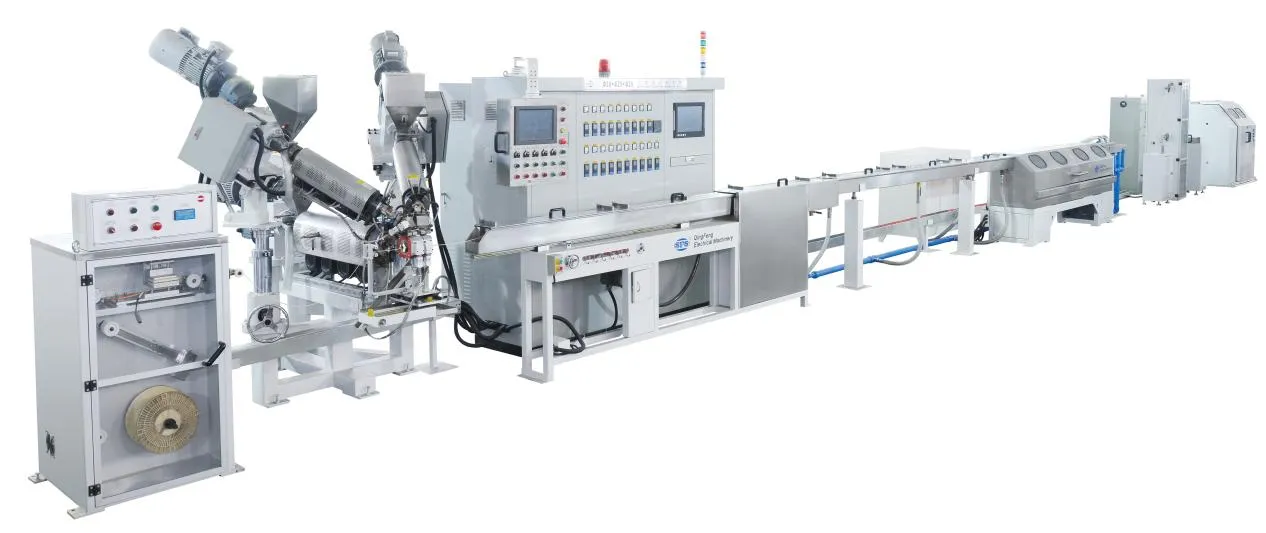
When an extruder requires frequent rebuilds, consumes excessive energy, or cannot maintain insulation concentricity at higher line speeds, modernizing the line becomes the more economical choice. Modern systems like Qingfeng extrusion line solutions feature wear-resistant bimetallic screws, integrated servo drives, and synchronized controls that significantly reduce scrap rates and lower overall maintenance demands.
Key Takeaways
Clearance Control is Paramount: Expanding screw-to-barrel clearances beyond 2.0x nominal levels degrades output, increases shear heat, and causes polymer degradation.
Calibrate Temperatures Regularly: Inspect and calibrate thermocouples and barrel heating bands monthly to prevent unmonitored thermal drift and jacket surface flaws.
Maintain Fluid Cleanliness: Preventative gearbox oil changes and closed-loop cooling water descaling prevent unexpected mechanical failures and drive surge.
Align Crosshead and Downstream Track: Misalignment between the extruder barrel, crosshead, cooling trough, and capstan leads directly to cable insulation eccentricity.
Track Cumulative Maintenance Costs: When rebuild costs exceed 40% of new equipment value and energy consumption impairs margins, line modernization provides a stronger return on investment.
Frequently Asked Questions (FAQ)
How often should the lubricant in an extruder gearbox be changed?
For new extrusion equipment, drain and replace the break-in gear oil after the first 500 operating hours. Following break-in, replace industrial synthetic gear lubricants every 4,000 to 5,000 operational hours or at least once per year, whichever comes first. Facilities operating under high ambient temperatures or continuous heavy loads should sample oil semi-annually to monitor viscosity, oxidation, and metallic particle contamination.
Can purging compounds eliminate the need to pull the screw during material changeovers?
Purging compounds clear out bulk polymer and transition pigments efficiently during routine color or resin changeovers. However, they do not remove hardened carbon buildup in flight dead zones or allow inspection of mechanical wear. Pulling and manually inspecting the screw is still necessary during scheduled annual maintenance to inspect flight integrity, evaluate barrel wear, and clean the root surface.
What causes repeated heater band burnout on an extruder barrel?
Heater band failures are typically caused by poor thermal contact with the barrel surface. As the barrel expands and contracts, loose clamps create microscopic air gaps. Air acts as a thermal insulator, preventing heat dissipation from the band into the barrel steel and causing the internal heating element to overheat and fail. Retorquing heater band clamps at operating temperature prevents this issue.
What is the most common cause of premature screw and barrel wear?
Processing abrasive compounds (such as highly filled flame-retardant LSZH or cross-linkable formulations) with standard nitrided screws instead of bimetallic alloys is the leading cause of accelerated abrasive wear. Cold starts—initiating screw rotation before polymers in the compression and metering zones are fully molten—also impose severe torsional and side-wall loads that cause flight galling.