Charging pile cable extrusion cannot be handled by a generic low-voltage power-cable line. The cable is repeatedly bent during charging-coupler mating, must pass flame-retardant and weathering tests, and is rated for either AC 250 V (slow charge) or DC up to 1000 V (fast charge). Those constraints change the insulation and sheathing material systems, the cleanliness of the extrusion environment, and the in-line quality control that buyers should require. This guide walks through the categories of EV charging cable, the choice between one combined insulation-and-sheathing line or two dedicated lines, the eight segments of a complete line, in-line QC priorities, and the questions to confirm with your supplier before signing.
Why Charging Pile Cables Need a Dedicated Extrusion Line
An EV charging cable is not just a “thicker power cable with a plug on the end.” Three application conditions drive the equipment requirements:
- Mechanical life: the cable is flexed at every plug-in and removal. Standard PVC-jacketed power cable fatigues fast under that duty.
- Thermal and flame-retardant load: fast-charging current through the conductor heats the insulation continuously, especially in liquid-cooled variants where coolant runs inside or alongside the cable core.
- Voltage class and safety standards: AC charging cables typically follow IEC 62893, while DC charging cables often reference EN 50620 and TÜV 2 PfG 1908. Those standards specify insulation resistance, dielectric withstand, and flame behaviour that the line must help the manufacturer hit consistently.
Material systems also differ from a commodity PE/PVC power-cable line. Common choices today include TPE, TPU, and XLPO (often crosslinked by electron-beam irradiation after extrusion) for insulation, and LSZH or low-friction TPU compounds for sheathing. These materials behave differently in the extruder: temperature windows are tighter, screw L/D selection changes, and some XLPO grades need a separate crosslinking step after the extruder. A line that was built for commodity house wiring will not reach the same insulation quality or yield on a charging-cable run.
For buyers evaluating a new line, that is the starting assumption behind every other choice below. If you are extending charging pile cable extrusion into a new product line, plan the line specifically for it rather than adapting an existing low-voltage line.
Cable Types and Their Equipment Implications
EV charging cables split into three families that drive different line segments:
AC slow- and moderate-charge cables (Mode 1 / Mode 2 / Mode 3)
Conductor sizes typically range from 2.5 to 16 mm², voltage up to AC 250 V, and continuous current usually below 32 A. The cable is lighter, more flexible, and the insulation wall is thinner. The line can run at higher linear speed, but the bending and abrasion resistance of the jacket still matters because the cable is dragged across the floor.
DC fast-charge cables (Mode 4)
Conductor sizes go up to 50, 70, or 95 mm², voltage up to DC 1000 V, and continuous current can reach 200–400 A. The conductor runs hot, so insulation must keep its dielectric strength at elevated temperature, and the jacket must survive outdoor UV. The line runs slower, with longer cooling and a larger capstan diameter to avoid bending the heavier core.
High-power liquid-cooled DC charging cables
Coolant runs in dedicated channels inside or alongside the conductor bundle. Process complexity rises: the cable core must accommodate coolant tubes without kinking, and the sheathing step must not collapse those channels. Some manufacturers braze or weld coolant tubes before extrusion; others co-extrude a multi-lumen profile.
The table summarises how each family maps to equipment choices. Treat the values as ranges for planning, not exact targets: line speed, conductor size, and insulation thickness should always be confirmed with the supplier against your specific cable design.
| Cable family | Typical conductor size | Common insulation | Equipment segment differences |
|---|---|---|---|
| AC slow/moderate charge | 2.5–16 mm² | TPE / XLPO | Standard 70–90 mm extruder, single line acceptable for combined insulation + sheathing at moderate output |
| DC fast charge | 16–95 mm² | XLPO, often EB crosslinked | Larger extruder (≥90 mm), longer cooling trough, double-capstan haul-off, dedicated crosslinking space |
| Liquid-cooled DC | 35–120 mm² with coolant channels | XLPO / special TPE | Pre-assembly station for coolant tubes, co-extrusion or sequential extrusion, precision tension control |
For background on how these cables fit into the broader wire-and-cable product mix, see the overview of cable applications across telecom, power, and new-energy lines.
Insulation vs Sheathing: One Line or Two?
This is one of the first decisions to lock down after you know which cable family you are producing. The two layers use different material systems, different cross-sections, and different cleanliness requirements. Combining them on a single line is possible in some cases, but the trade-offs are real.
Insulation is the inner layer in direct contact with the conductor. It must be a clean, low-contamination compound with tight dielectric control, often XLPO or TPE. Sheathing is the outer jacket that handles abrasion, flame retardancy, and weather resistance; LSZH or low-friction TPU are common choices.
Use a combined insulation + sheathing line when:
- The conductor size is small to mid-range (up to about 16 mm²) and the line speed stays moderate.
- You are running a single cable family with consistent material combinations.
- Floor space and operator headcount are tight.
Use separate insulation and sheathing lines when:
- You produce both AC and DC charging cables and want different screw geometries or temperature profiles for each layer.
- The insulation uses EB-crosslinked XLPO that needs a separate crosslinking stage between extrusion and sheathing, since a combined line cannot host irradiation equipment inline.
- Your planned volume is high enough that two single-purpose lines beat one flexible line on cycle time.
The right answer depends on your product mix, not on a generic “best practice.” For DC fast-charge cables, the EB crosslinking step is often the deciding factor that pushes manufacturers toward separate insulation and sheathing stations.

Line Configuration: from Pay-Off to Take-Up
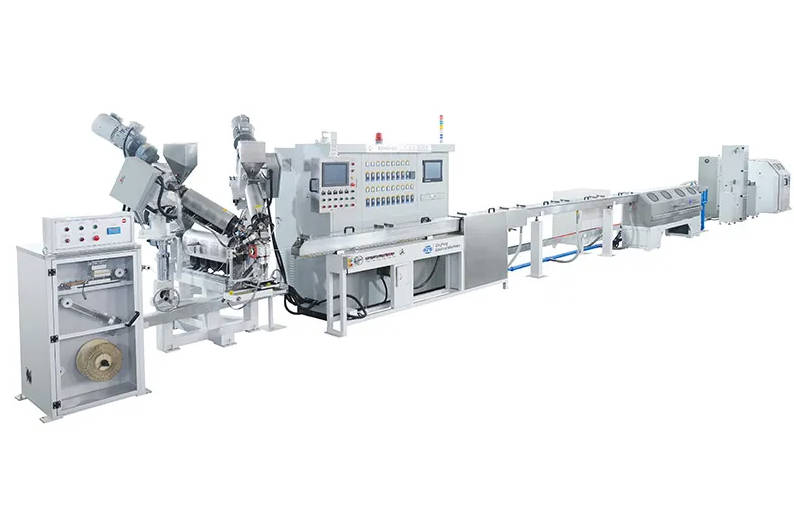
An EV charging-cable extrusion line is a chain of eight segments. Each segment has a specific role, and most are similar to a generic power-cable line, with two notable additions for charging cables.
| Segment | Role | Key control point | Notes for EV charging cable |
|---|---|---|---|
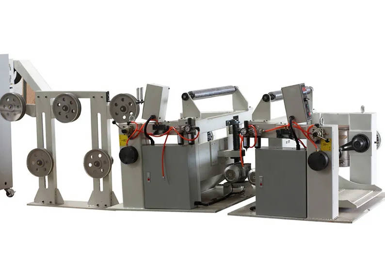
| 1. Pay-off | Feeds conductor from spool | Tension stability, dancer control | Use a pay-off matched to the spool size and conductor diameter |
| 2. Preheater / annealer | Removes moisture and stress-relieves the conductor | Temperature uniformity across the bundle | Skip for fine single-wire AC charging conductors |
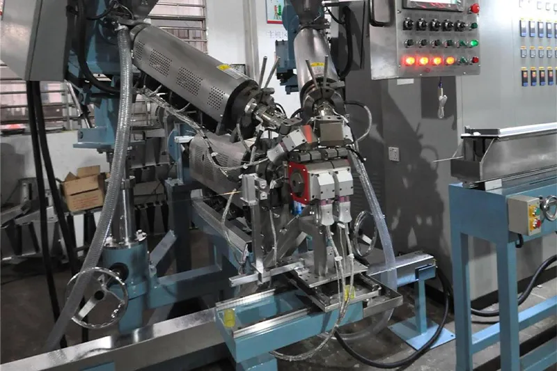
| 3. First extruder + crosshead | Insulation extrusion | Melt temperature, screw speed, line speed ratio | Use a screw L/D matched to XLPO or TPE; tight eccentricity control needed |
| 4. Cooling trough 1 | Solidifies insulation | Water temperature, immersion length | Longer trough for thicker DC insulation walls |
| 5. In-line QC station | Diameter, eccentricity, spark test, capacitance | Sensor calibration, spark voltage | Detailed in the next section |
| 6. Second extruder (sheathing) | Outer jacket | Melt temperature, concentricity | Required when insulation and sheathing are split across stations |
| 7. Printer / marker | Prints voltage class, standard, batch code on the jacket | Ink adhesion, print clarity | Especially important for outdoor UV-rated jackets |
| 8. Capstan + take-up | Sets line speed and winds the finished cable | Line-speed stability, traverse pitch | Larger capstan for heavier DC cores |
Two segments above (the printer and, in many DC lines, a crosslinking zone between the first extruder and the second extruder) are the ones that differ most from a generic power-cable line. Plan floor space and cable path for them before the rest of the layout is fixed. For a full overview of how the segments fit together, see how an extrusion line is laid out end to end.

In-Line Quality Control for EV Charging Cables
Charging cables carry safety-relevant current at elevated voltage, so on-line QC is not optional. Six measurements and tests are the minimum to build into the line:
- Insulation outside diameter and concentricity: continuous laser micrometer or X-ray head. Tight concentricity is needed for stable dielectric strength, especially in DC fast-charge cables.
- Spark test on insulation: typically 3–6 kV AC, depending on insulation thickness and standard. Sparks pinholes or thin spots before the jacket covers them.
- Capacitance / impedance scan on the insulated core: catches foaming or material inconsistencies that would drift the cable’s electrical performance.
- Sheath outside diameter and concentricity: same laser or X-ray station after the jacket extruder.
- Spark test on the sheathed cable: lower voltage than the insulation test, but still mandatory to catch jacket damage.
- Flame-retardant sample retention: cut length samples at the start, middle, and end of each batch for vertical or horizontal flame tests in the lab. Online sensors cannot replicate the standard flame test, so sample retention is the practical bridge to certification.
Most of these QC stations can be added to a standard power-cable line, but they need to be specified up front, not retrofitted. Adding a continuous capacitance scan or a sample-retention cut after the line is built is more expensive than specifying it in the RFQ.
What to Confirm with Your Supplier
Before signing the purchase order, walk through this checklist with the supplier. It covers commercial, technical, and documentation items that often get missed until installation day.
- Acceptance test scope and conditions: which IEC / EN / TÜV standards will be demonstrated at FAT, and which are the buyer’s responsibility at SAT.
- Reference cable recipes: number of pre-set recipes (conductor size × insulation material × sheathing material) included in the controller, and the process for adding new ones.
- Spare parts list: critical wear parts (screws, barrels, crosshead tips, spark electrodes, capstan belts) and their recommended replacement interval.
- Training and installation: who installs the line on site, how many days of operator training are included, and whether the supplier provides a commissioning engineer in person.
- Documentation package: mechanical drawings, electrical schematics, PLC source, P&ID, and CE / declaration files in editable formats.
- Warranty and response time: warranty period on mechanical and electrical components, and the supplier’s stated response time for remote and on-site support.
- Future-proofing: ability to add a printer, a second extruder, or an irradiation device later without rebuilding the line.
For buyers who want help evaluating trade-offs between suppliers or matching this checklist to a specific cable family, cable machinery solutions and after-sales service from an experienced equipment maker can save weeks of back-and-forth at the RFQ stage.
FAQ
Can a PV cable extrusion line also produce EV charging cables?
It depends on the cable design. Both families use crosslinked insulation and weather-resistant jackets, so a PV line can be a starting point. However, charging cables have higher mechanical-flex life requirements and different standard coverage (IEC 62893, EN 50620, TÜV 2 PfG 1908), so the line usually needs at least a new spark tester setting, a new recipe library, and usually a longer cooling trough. Treat PV-to-charging conversion as a re-specification, not a drop-in change.
Do AC and DC charging cables need separate lines?
Not always. Some factories run both on a single flexible line with recipe changes. The deciding factors are line-speed difference, conductor size, and whether the DC line uses EB crosslinking. Where DC requires a separate crosslinking stage, an AC-only line cannot host it, so the two products effectively need separate stations or a longer combined line.
How is the flame-retardant grade verified during production?
On-line sensors can verify geometry and electrical integrity, but the flame test itself is destructive and must be run in a lab on cut samples. The standard practice is to retain length samples at defined intervals during the run and run vertical or horizontal flame tests per the relevant standard. Document each batch’s sample test results so they can be traced back to the production run.
What output should I expect from an EV charging cable extrusion line?
Output depends on line speed, conductor size, insulation thickness, and whether sheathing shares the same line. Faster lines are possible on small AC charging conductors; DC fast-charge lines run slower because of the larger insulation wall and longer cooling path. Confirm specific output figures with the supplier against your target cable design rather than relying on generic catalog values.
Conclusion
A dedicated charging pile cable extrusion line is justified by the mechanical-flex life, thermal load, and safety standards of EV charging cables. The right line configuration flows from the cable family you produce: AC and DC families need different screw geometries and cooling paths, and DC fast-charge often requires an EB crosslinking step that pushes insulation and sheathing to separate stations. Quality control is non-negotiable, with on-line diameter, spark, and capacitance checks plus sample retention for flame tests. The supplier’s RFQ response should cover acceptance tests, recipe libraries, spare parts, training, documentation, warranty, and future upgrade paths.
For a configuration review or quotation, share the target cable family (AC slow charge, DC fast charge, or liquid-cooled DC), the conductor size range you plan to run, the standards you intend to certify against (IEC 62893, EN 50620, TÜV 2 PfG 1908), and the expected annual volume. With those inputs, an experienced equipment maker can map the eight segments above to your specific line and flag the trade-offs that matter for your product mix.