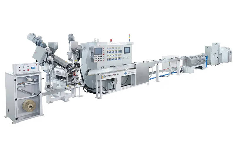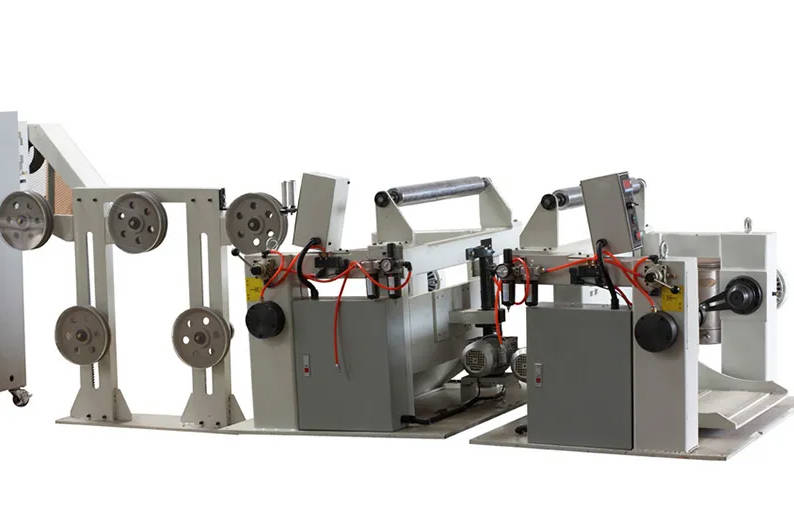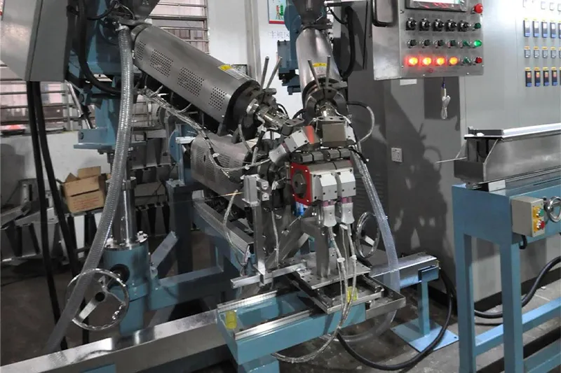
A mica tape wrapping machine for fire-resistant cable must apply a continuous, crack-free and correctly overlapped insulation barrier around the conductor or cable core. Its real value is not maximum rotational speed, but its ability to maintain tape tension, coverage and layer integrity throughout production.
Mica tape is commonly used as a fire-resistant electrical insulation layer in power, control, emergency, alarm and other cables that are expected to maintain circuit integrity under defined fire conditions.
That requirement is different from ordinary flame retardancy. The IEC 60331 series addresses cables required to maintain circuit integrity when exposed to fire and, for some test methods, mechanical shock. The IEC 60332 series evaluates resistance to flame propagation. A cable may therefore limit flame spread without necessarily continuing to carry electrical current during a fire.
For cable manufacturers, this distinction changes how the wrapping process should be evaluated. The machine is not merely covering a conductor with tape. It is creating a protective insulation path that must remain sufficiently continuous after the cable’s outer polymer layers have been damaged by heat.
Manufacturers developing this production capability can review QingFeng SFS mica tape wrapping machine solutions for single-head, multi-head and customized cable taping configurations.
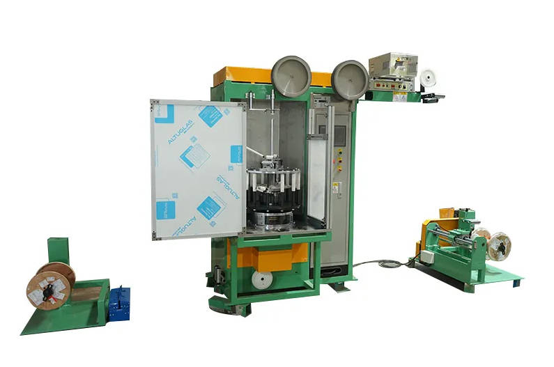
Begin With the Failure That Must Be Prevented
A fire-resistant cable can fail even when mica tape is present.
The mica layer may not provide the expected protection when it contains:
- Gaps between adjacent turns
- Cracked or torn tape
- Folded tape edges
- Unstable overlap
- Local areas with excessive tension
- Loose wrapping that shifts during extrusion
- Exposed conductor at starts, stops or joints
- Misalignment between multiple tape layers
- Damage caused by guides or pulling equipment
- Contamination or fragments trapped under the tape
This leads to a more useful machine-selection question:
Can the proposed machine maintain a continuous mica barrier under the actual tape, conductor, overlap and production-speed conditions?
Fire-resistant cable performance begins with wrapping continuity. A high-speed machine cannot compensate for gaps, tears or unstable overlap in the mica layer.
The Cable Fire Test Determines the Wrapping Objective
The target cable standard or customer specification should be confirmed before the machine configuration is finalized.
The project team needs to define:
- Cable voltage rating
- Conductor size range
- Cable construction
- Required fire-test method
- Whether mechanical shock is included
- Whether water spray or water jet conditions are relevant
- Required circuit-integrity duration
- Single-core or multi-core design
- Mica tape material and backing
- Number of mica layers
- Required overlap
- Insulation and jacket materials applied after taping
IEC 60331 test methods differ according to factors such as cable voltage and overall diameter. The correct test requirement should therefore come from the finished cable specification rather than from a general claim that the cable is “fireproof.” (IEC Webstore)
Fire-Performance Terms Should Not Be Mixed
| Term | Main Performance Question | Manufacturing Implication |
| Flame retardant | Does the cable limit flame propagation? | Jacket and insulation compounds are major factors |
| Fire resistant | Does the cable maintain circuit integrity during fire exposure? | Continuous high-temperature electrical insulation becomes critical |
| Low smoke | How much smoke is generated during combustion? | Polymer compound selection is important |
| Halogen free | Does the cable avoid halogen-containing materials? | Material formulation and the full cable construction must be considered |
| Fire resistant with mechanical shock | Can the energized cable continue operating during fire and impact? | Mica-layer continuity and structural stability are especially important |
Mica tape is normally associated with circuit integrity, but the final performance belongs to the complete cable construction. Conductor size, tape system, insulation, fillers, sheath and cable assembly all influence the test result.
The Mica Tape Is a Composite Material, Not Just a Mineral Layer
Commercial cable mica tapes typically combine mica paper with a reinforcement layer and a heat-resistant binder.
Possible constructions include:
- Mica paper with single-sided glass-fabric backing
- Mica paper with double-sided glass reinforcement
- Mica paper with polymer-film backing
- Mica paper with combined glass fabric and film
- Phlogopite mica tape
- Calcined muscovite mica tape
- Synthetic mica tape
Published product ranges show that mica tapes may use glass fabric, polymer film or combined backing structures, with different thicknesses, widths, roll lengths and mechanical characteristics.
These differences directly affect the wrapping machine.
How Tape Construction Changes Machine Requirements
| Tape Characteristic | Production Risk | Machine Requirement |
| Thin mica layer | Cracking or local damage | Smooth tape path and low-inertia tension control |
| Glass-fabric backing | Edge fraying or dust | Clean guides and controlled tape alignment |
| Film backing | Slippage or static | Stable guidance and adjustable brake or drive control |
| Brittle tape | Breakage during acceleration | Gradual speed ramping and tape-break detection |
| Wide tape | Wrinkling on small conductors | Correct tape angle and forming-point control |
| Heavy roll | High rotational inertia | Balanced head and sufficient drive capacity |
| Short pad length | Frequent machine stops | Fast, accessible roll-change design |
| Long spool package | Higher continuous output | Compatible spindle, traverse and tension system |
A machine trial should use the intended mica tape construction and package format. Testing with ordinary polyester tape does not show how brittle mica tape will behave under actual production tension.
The Wrapping Window Has Four Interdependent Variables
Mica wrapping quality is governed by four variables:
- Cable linear speed
- Taping-head rotational speed
- Tape width and wrapping angle
- Tape tension
Changing one variable changes the others.
For example, increasing cable speed without increasing head rotation changes the wrapping pitch. Increasing tape tension may reduce wrinkles but can also stretch, crack or tear the tape. Changing tape width affects both coverage and material consumption.
Overlap, rotational speed, line speed and tape tension must be treated as one coordinated process rather than four independent machine settings.
Why Overlap Matters
Adjacent turns of mica tape usually overlap to prevent a direct gap through the fire-resistant layer.
If the overlap is too low:
- Small speed variations may create exposed areas
- Cable movement may open local gaps
- Tape-width variation becomes more critical
- The next extrusion process may shift the layer
If the overlap is unnecessarily high:
- Mica consumption increases
- Finished cable diameter increases
- The layer becomes less flexible
- The surface may become uneven
- More heat may be required during later extrusion
- Production speed may decrease
The required overlap should come from the cable design and validation process. It should not be selected only from a standard machine recipe.
Why Actual Coverage Can Differ From the HMI Value
A control screen may display a calculated overlap, but the finished layer can still be unstable because of:
- Tape stretching
- Tape slipping on guides
- Cable-speed variation
- Taping-head speed fluctuation
- Changing tape-roll diameter
- Cable vibration
- Incorrect forming-point position
- Tape-width tolerance
- Conductor ovality
The machine should therefore be evaluated by measuring the wrapped cable, not only by reviewing displayed settings.
Tension Is the Most Sensitive Part of Mica Wrapping
Mica tape must be held tightly enough to follow the conductor but gently enough to avoid cracking.
This creates a narrower process window than many ordinary binding tapes.
Too Much Tension Can Cause
- Tape breakage
- Cracking of the mica paper
- Narrowing or stretching of the backing
- Conductor deformation
- Reduced overlap
- Irregular tape edges
- Frequent production stops
Too Little Tension Can Cause
- Loose wrapping
- Wrinkles
- Layer movement
- Variable cable diameter
- Poor entry into the extrusion crosshead
- Trapped folds under the insulation
- Unstable overlap
Tape tension may also change as the roll becomes smaller. A full roll and a nearly empty roll have different diameters and rotational inertia.
Tension-Control Options
| Control Method | Main Characteristic | Suitable Evaluation Question |
| Mechanical friction brake | Simple structure | Does tension remain stable as the roll diameter changes? |
| Magnetic-powder brake | Adjustable braking torque | Can it control the required low-tension range without overheating? |
| Dancer system | Compensates for tension variation | Is the dancer responsive enough for brittle mica tape? |
| Servo-driven tape payoff | Actively controls tape delivery | Does it remain stable during acceleration and deceleration? |
| Load-cell feedback | Measures tension directly | Where is tension measured, and how is the sensor calibrated? |
| Combined dancer and feedback control | Provides compensation and measurement | Can recipes be stored for different mica tape types? |
QingFeng SFS lists high-sensitivity dancers, load-cell tension checking, automatic full-to-empty bobbin tension adjustment and speed-synchronism or wire-break detection among available taping-machine functions. (dgqfmachine.com)
One Layer or Two Layers?
The required number of mica layers depends on the cable structure, selected tape and target fire-test performance.
A single layer reduces material use and cable diameter, but it provides less redundancy if a local gap or defect occurs.
Two mica layers can improve coverage by placing the second layer over possible weak points in the first. However, the machine must control both layers independently.
Single- and Double-Layer Comparison
| Configuration | Advantages | Main Risks | Appropriate Situation |
| Single-layer wrapping | Lower tape consumption, smaller cable diameter and simpler setup | Local defects have less backup coverage | Validated cable design using suitable tape and controlled wrapping |
| Two layers in the same direction | Simple directional setup | Gaps may align if both layers follow similar geometry | Product-specific constructions where alignment is controlled |
| Two layers in opposite directions | Better cross-coverage of local gaps | More complex head synchronization | Fire-resistant cable requiring redundant mica coverage |
| Multiple independent passes | Each layer can be inspected separately | More handling, floor space and production time | Flexible production or separate quality-control stages |
| Multi-head inline wrapping | Several layers in one pass | Higher control and setup complexity | Higher-volume production with stable product specifications |
For multi-layer mica wrapping, each head should allow independent adjustment of direction, tension, rotational speed and tape package.
The machine supplier should not assume that every double-layer cable uses identical tape tension or overlap on both heads.
Horizontal, Vertical or Concentric Machine?
The preferred machine architecture depends on conductor size, tape package and production layout.
Horizontal Mica Taping Machine
A horizontal system provides a straight cable path and can be integrated with larger payoff, puller and take-up units.
It is commonly considered for:
- Power cable conductors
- Larger cable cores
- Multi-head wrapping
- Long production lines
- Heavier reels
- Integration before extrusion
Important evaluation points include rotating balance, cable support, machine footprint and access to each head.
Vertical Mica Taping Machine
A vertical arrangement may offer a more compact footprint or suitable tape-package orientation for certain conductors.
It may be useful for:
- Smaller wire
- Specialized production layouts
- Fine cable structures
- Limited floor space
Operator access, machine height, tape loading and tension behavior should still be tested with the actual product.
Concentric Multi-Head System
A concentric system places one or more rotating tape heads around a relatively stable cable path.
It is suitable when the manufacturer requires:
- Two or more mica layers
- Opposite wrapping directions
- Independent tape tension
- Continuous production
- Consistent cable center position
The correct architecture should be selected from the cable and tape package—not from a general assumption that one orientation is always faster.
The Equipment Around the Taping Head Also Determines Quality
A complete fire-resistant cable taping machine may contain:
- Conductor payoff
- Accumulator or dancer
- Straightening unit
- Cable cleaning system
- One or more mica taping heads
- Tape-break detection
- Compaction or forming device
- Capstan or caterpillar puller
- Diameter or surface inspection
- Accumulator
- Take-up system
- PLC and HMI control
Payoff
The payoff must handle the conductor reel without causing abrupt changes in cable tension.
Large power conductors may require:
- Motorized payoff
- Heavy-reel loading
- Controlled braking
- Accumulation for reel changes
- Accurate center alignment
Pulling Unit
The capstan or caterpillar establishes cable linear speed. Any slipping changes the relationship between line speed and head rotation, which can alter wrapping pitch.
The pulling system should provide sufficient force without flattening or marking the wrapped conductor.
Compaction
A forming or compacting unit may help stabilize the mica layer before the cable enters the next manufacturing process.
The pressure must remain controlled. Excessive compaction can damage brittle tape, while insufficient compaction may allow the layer to loosen.
Take-Up
The finished reel should be wound with enough tension to remain stable but not so much that the mica layer shifts or the conductor is deformed.
What Happens After Mica Wrapping?
Mica taping is normally one stage within a larger cable production route.
A simplified process may include:
- Conductor preparation
- Mica tape wrapping
- Insulation extrusion
- Core assembly
- Additional fire barrier or bedding
- Metallic shielding or armoring where required
- Outer sheath extrusion
- Printing and marking
- Electrical testing
- Fire-resistance validation
The wrapped conductor must enter the extrusion crosshead without disturbing the mica layer.
Common problems between taping and extrusion include:
- Tape loosening during reel transfer
- Tape edges lifting
- Layer movement at the payoff
- Excessive conductor bending
- Damage caused by guides
- Moisture or dust contamination
- Insulation pressure shifting the mica layer
Where possible, inline taping and extrusion can reduce intermediate handling. However, the complete line must be synchronized and allow sufficient access for tape-roll replacement.
Read the Defect Before Changing Machine Settings
| Observed Defect | Likely Cause | First Areas to Check |
| Gaps between turns | Incorrect pitch, speed mismatch or low overlap | Head speed, line speed and tape width |
| Tape breakage | Excessive tension, sharp guides or abrupt acceleration | Brake, dancer, tape path and speed ramp |
| Wrinkled tape | Low tension, poor alignment or incorrect wrapping angle | Guide position, forming point and cable centering |
| Folded tape edge | Excessive tape angle or unstable tape path | Tape guide and head alignment |
| Changing overlap | Tape stretching, speed fluctuation or roll-diameter effect | Tension control, puller and synchronization |
| Loose layer | Insufficient tension or compaction | Dancer setting and forming unit |
| Tape dust | Abrasion, sharp guides or unsuitable handling | Guide surfaces and tape path |
| Mica cracking without full break | Tension peaks or tight bending radius | Tension trend and guide geometry |
| Layer movement during extrusion | Loose wrapping or poor transfer handling | Compaction, take-up and extrusion payoff |
| Misaligned second layer | Head synchronization or cable movement | Independent head settings and center guides |
Only one major parameter should be changed at a time during troubleshooting. Simultaneously changing tension, speed and overlap makes it difficult to identify the real cause.
Prepare the RFQ Around the Fire-Resistant Cable
A useful request for quotation should include the following details.
| RFQ Category | Required Information |
| Cable application | Power, control, alarm, emergency, instrumentation or other cable |
| Target standard | Applicable fire-resistance and cable construction requirements |
| Conductor | Copper or aluminum, solid or stranded |
| Conductor size | Minimum and maximum diameter or cross-section |
| Mica type | Phlogopite, muscovite, synthetic or specified product grade |
| Tape construction | Glass-backed, film-backed or other composite |
| Tape size | Width, thickness, roll OD, core ID and roll length |
| Layer design | Number of layers and wrapping direction |
| Coverage | Required overlap, pitch or taping angle |
| Tension | Target range or finished-layer requirement |
| Production speed | Required stable line speed |
| Reel information | Payoff and take-up reel sizes and weights |
| Inline process | Standalone taping or integration with extrusion |
| Detection | Tape break, conductor break, tension, vision or diameter |
| Data | Recipes, alarm history, reports and parameter export |
| Factory conditions | Voltage, frequency, floor space and utilities |
| Acceptance test | Actual conductor, tape and measurable pass criteria |
QingFeng SFS offers cable taping equipment for mica and other insulation materials with horizontal, vertical and multi-head configurations. Its wider wire and cable machinery capabilities can support integration with payoff, pulling, take-up and subsequent cable processes.
Factory Acceptance Testing: Deliberately Challenge the Process
A factory acceptance test should not only run the easiest conductor at a moderate speed.
The test should challenge the machine with the most sensitive combination of tape, conductor and operating condition.
Recommended FAT Sequence
- Verify the actual tape package fits the spindle
- Thread the complete tape path
- Record starting tape tension
- Run the conductor at low speed
- Establish the forming point
- Measure initial overlap
- Increase to the agreed operating speed
- Check tape integrity and surface quality
- Test acceleration and deceleration
- Test tape-break detection
- Repeat with a smaller tape-roll diameter
- Test each head independently
- Run all heads simultaneously
- Inspect opposite-direction layer coverage where applicable
- Review reel winding and cable transfer
- Retrieve recipes and alarm records
- Demonstrate cleaning and tape changeover
- Confirm continuous operation for the agreed test period
Use the Most Difficult Production Condition
The trial should include one or more of the following:
- Smallest conductor
- Largest conductor
- Thinnest mica tape
- Widest mica tape
- Most brittle tape
- Highest overlap
- Lowest permitted tension
- Maximum required line speed
- Opposite-direction double wrapping
- Heaviest tape package
The FAT should prove continuous mica coverage at the agreed production speed, not merely demonstrate the machine’s unloaded rotational speed.
Conclusion
A mica tape wrapping machine creates the fire-resistant insulation barrier that protects the conductor after ordinary polymer insulation begins to fail under heat.
Its performance depends on the relationship between the cable, tape construction, overlap, tension, rotational speed and line speed.
The correct machine must:
- Handle the specified mica tape without cracking it
- Maintain overlap from full roll to empty roll
- Keep tension stable during speed changes
- Apply multiple layers without aligned weak points
- Detect tape breakage quickly
- Deliver a stable wrapped conductor to the next process
- Record recipes and production abnormalities
The most suitable mica taping machine is the one that repeatedly produces a continuous, stable and validated mica layer—not simply the machine with the highest RPM.
Cable manufacturers can discuss a customized mica tape wrapping machine with QingFeng SFS based on their conductor range, tape specification, layer design and production target.
Frequently Asked Questions
What is a mica tape wrapping machine used for?
A mica tape wrapping machine applies one or more mica insulation layers around a conductor or cable core. The wrapped layer helps the finished cable maintain electrical circuit integrity under specified fire conditions.
What is the difference between fire-resistant and flame-retardant cable?
A fire-resistant cable is designed to continue carrying current for a specified period under defined fire conditions. A flame-retardant cable is designed primarily to limit flame propagation. The applicable test methods and cable structures are different.
Which mica tape is used for fire-resistant cables?
Fire-resistant cables may use phlogopite, calcined muscovite or synthetic mica tape. These tapes may be reinforced with glass fabric, polymer film or combined backing. Selection depends on the cable design and required test performance.
How much overlap is required for mica tape wrapping?
The required overlap depends on tape width, conductor diameter, number of layers and the validated cable design. It should be defined by the product specification rather than assumed from a universal value.
Why does mica tape break during high-speed wrapping?
Common causes include excessive tension, sharp tape guides, poor roll quality, high rotational inertia, abrupt acceleration and incorrect tape-path alignment.
Is a double-layer mica taping machine better than a single-layer machine?
A double-layer machine can provide more complete coverage and allow opposite-direction wrapping, but it also requires more complex tension and synchronization control. The correct configuration depends on the cable design.
Can mica tape be wrapped directly on a stranded conductor?
Yes, but the conductor surface, strand stability, tape tension and wrapping angle must be controlled. An irregular conductor surface can increase the risk of tape damage or uneven coverage.
What tension control is suitable for a mica taping machine?
Possible systems include mechanical brakes, magnetic-powder brakes, dancers, servo-driven payoffs and load-cell feedback. The correct system depends on the tape’s brittleness, roll inertia and required production speed.
Can mica taping be integrated with an extrusion line?
Yes. Inline integration can reduce intermediate handling, but taping-head speed, cable tension, tape replacement and extrusion-line speed must be coordinated.
How should a mica tape wrapping machine be tested before purchase?
It should be tested using the intended conductor and actual mica tape. The trial should evaluate overlap, tension, tape breakage, speed transitions, multiple-head synchronization and continuous production.