In the era of 5G telecommunications, hyperscale data centers, and advanced aerospace electronics, the demand for high-frequency signal integrity has never been higher. As frequencies push into the millimeter-wave (mmWave) spectrum, even the slightest physical imperfection in a cable can lead to catastrophic signal degradation.
For cable manufacturers, the challenge is clear: minimizing return loss is the primary goal for producing high-performance coaxial and data cables. While material science plays a role, the mechanical precision of the high-speed taping machine is often the deciding factor in whether a cable meets stringent international standards or ends up in the scrap bin.
Understanding Return Loss and Impedance Consistency
Return Loss (RL) is a measure of the power reflected back toward the source due to discontinuities in a transmission line. In a perfect world, all energy sent through a cable would reach the destination. In reality, any change in the cable’s physical structure—such as variations in the dielectric thickness or the wrapping density of the shield—creates an impedance mismatch.
The Physics of Signal Reflection
Characteristic impedance ($Z_0$) in a high-frequency cable is determined by the ratio of the conductor diameters and the dielectric constant ($\epsilon_r$) of the insulation. The formula is generally expressed as:
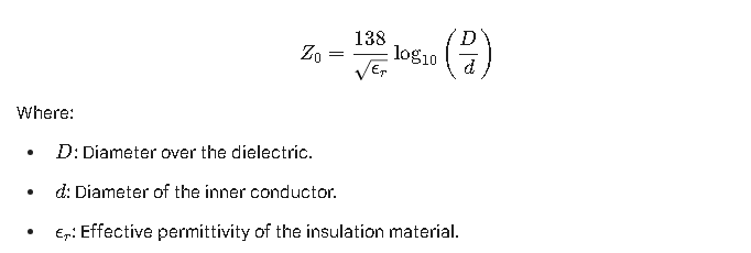
High-speed taping machine stability is the critical variable that maintains a constant $D$ and $\epsilon_r$ across the entire length of the cable. If the machine vibrates or the tension fluctuates, the tape may stretch or overlap unevenly, causing local spikes in impedance that manifest as poor return loss.
How Taping Instability Causes Return Loss
When operating a high-speed taping machine at speeds exceeding 2,500 RPM, mechanical stability becomes a complex engineering challenge. Instability manifests in three primary ways that directly impact signal integrity:
1. Tension Fluctuations and “Necking”
High-speed taping machine stability is essential because inconsistent tape tension causes “necking” or compression of the cable core, which directly alters the cable’s characteristic impedance and increases return loss. If the tension is too high, the dielectric is crushed, reducing the diameter ($D$). If it is too low, the tape may “birdcage” or gap, creating air pockets that change the effective $\epsilon_r$.
2. Overlap Irregularity
Precise overlap (often 25% to 50%) is required for shielding and insulation. Mechanical jitter in the taping head causes the “pitch” to vary. In high-frequency applications, these periodic variations act like a diffraction grating for electromagnetic waves, causing signal reflections at specific resonant frequencies.
3. Mechanical Resonance and Vibration
At high RPMs, any imbalance in the taping head creates micro-vibrations. These vibrations are “recorded” into the physical structure of the cable as periodic deformations. For 5G cables, where wavelengths are measured in millimeters, even a 10-micron deformation can cause a measurable drop in RL performance.
Key Features of High-Stability High-Speed Taping Machines
To combat these issues, modern high-speed taping machines incorporate several advanced technical features designed specifically for the production of low-loss cables.
Active Tension Control Systems
Unlike traditional mechanical brakes, high-end machines use servo-driven active tension control. These systems utilize ultra-sensitive dancer arms or load cells to monitor tension in real-time, adjusting the payoff speed thousands of times per second to maintain a constant centinewton (cN) value.
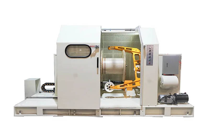
Precision Concentric Taping Heads
A concentric head ensures that the center of gravity remains on the axis of rotation. This minimizes centrifugal forces that could lead to head “wobble.” High-stability machines often use carbon-fiber components for the taping arms to reduce mass and increase the resonance frequency.
Integrated PLC and HMI Systems
Advanced Programmable Logic Controllers (PLC) synchronize the linear line speed with the rotational speed of the taping head. This ensures that the wrapping pitch remains identical during acceleration and deceleration phases, a common point of failure for lower-quality machines.
Comparative Data: Mechanical vs. Servo-Driven Stability
The following table illustrates the performance differences between standard mechanical taping machines and high-stability servo-driven systems in the production of PTFE-taped coaxial cables.
| Feature | Standard Mechanical Machine | High-Stability Servo Machine | Impact on Return Loss |
| Max Head Speed | 800 – 1,200 RPM | 2,500 – 5,000 RPM | Productivity & Throughput |
| Tension Precision | ± 15% | ± 1.5% | Eliminates impedance “necking” |
| Overlap Accuracy | ± 0.5 mm | ± 0.05 mm | Prevents resonant reflections |
| Vibration (G-force) | High (>2G) | Ultra-low (<0.2G) | Maintains physical concentricity |
| Typical RL (@ 18GHz) | -15 dB to -18 dB | -25 dB to -30 dB | Significantly better signal integrity |
Operational Strategies for Minimizing RL
Even with the best equipment, operational stability is required to achieve peak performance.
- Dynamic Calibration: Regularly calibrate the tension sensors using precision weights. To minimize return loss in high-frequency cables, manufacturers must ensure that the high-speed taping machine is calibrated for the specific elasticity of the tape material, such as PTFE or Kapton.
- Environmental Control: Temperature fluctuations can change the viscosity of lubricants and the elasticity of tapes. Maintaining a climate-controlled production floor ensures consistent machine behavior.
- Tooling Maintenance: Ensure that guiding rollers are free of debris. Any friction in the path of the tape will introduce “tension spikes” that the servo system may not be able to fully damp out.
Addressing Common User FAQs
Why is my cable failing Return Loss tests even though the tape looks uniform to the eye?
Visual uniformity is insufficient for high-frequency cables. RL failures are often caused by “periodic defects”—tiny, repeating variations in tension or pitch that match the wavelength of the signal. High-speed taping machines with high mechanical stability eliminate these periodic errors by using electronic gearing to lock the rotation and line speed together.
Can I run my machine at maximum speed without affecting cable quality?
It depends on the machine’s vibration damping. Most machines have a “sweet spot.” Beyond a certain RPM, mechanical resonance occurs. Investing in a machine with a high-stability frame and vibration-dampening base allows you to push the speed limits without sacrificing the RL plot.
What is the best tape material for high-frequency stability?
Expanded PTFE (ePTFE) is the industry standard due to its low dielectric constant. However, it is highly sensitive to stretching. For these materials, a machine with zero-tension or ultra-low tension control is mandatory to prevent the tape from narrowing during application.
Conclusion: The ROI of Machine Stability
In the competitive world of cable manufacturing, the difference between a high-margin premium product and a low-grade commodity is signal performance. Investing in a high-speed taping machine with superior stability is the most effective way to reduce scrap rates and meet the rigorous Return Loss requirements of next-generation electronics. Stability is not just a mechanical feature; it is the fundamental requirement for signal integrity in the digital age.