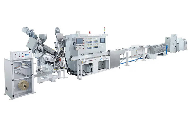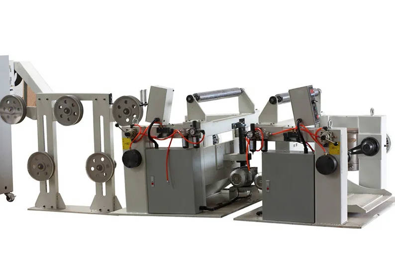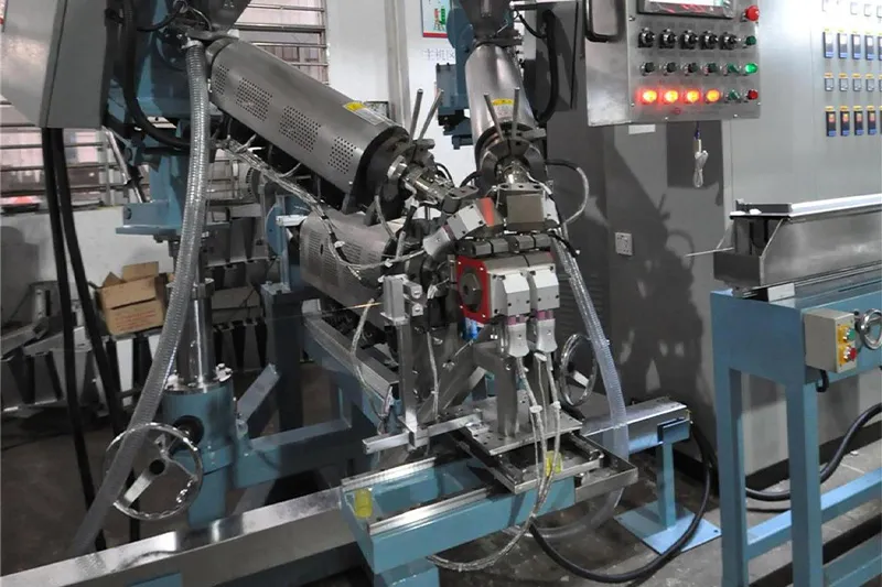
A Teflon extrusion line for high-temperature wire is not simply a standard cable extruder fitted with stronger heaters. It must be configured around the actual fluoropolymer, conductor size, insulation structure, dimensional tolerance and required production speed.
In commercial searches, “Teflon extrusion line” is often used as a general term for equipment processing fluoropolymer insulation. However, FEP, PFA, ETFE and PTFE do not all follow the same extrusion route. FEP, PFA and ETFE are melt-processable materials, while conventional PTFE fine powder is normally processed through paste extrusion followed by drying and sintering. Treating these materials as interchangeable can lead to an incorrect machine specification before a project even begins. ble manufacturer, the correct starting point is therefore not the extruder model. It is the finished wire: what environment it will operate in, which resin grade will be used, how thin the insulation must be, what electrical properties must be controlled and how the product will be inspected.
QingFeng SFS provides Teflon and high-temperature cable extrusion solutions for different wire structures, including fluoropolymer insulation and physical foaming applications.
Start With the Finished Cable, Not the Extruder
Two factories may both request a “Teflon extrusion line” while actually needing very different equipment.
One factory may produce thin FEP-insulated electronic wire with strict outside-diameter control. Another may require PFA insulation for cable exposed to higher service temperatures and chemicals. A third may manufacture PTFE-insulated coaxial cable using paste extrusion rather than conventional melt extrusion.
The following questions should be answered before machine configuration begins:
- What conductor material and conductor size will be processed?
- Is the conductor solid, stranded, plated or bare?
- Which exact fluoropolymer grade will be used?
- Is the insulation solid, chemically foamed or physically foamed?
- What are the target insulation thickness and finished outside diameter?
- What tolerances apply to diameter, wall thickness and concentricity?
- Is the cable designed for power transmission, signal transmission or both?
- Which online inspection instruments are required?
- What reel sizes, production speed and factory layout must the line support?
The equipment should be engineered backward from these finished-product requirements rather than selected from a generic machine catalogue.
Material and Process Route Comparison
| Material | Typical Processing Route | Common Cable Use | Main Equipment Implication |
| FEP | Melt extrusion | Thin wire insulation, electronic wire, communication cable and cable jackets | High-temperature extrusion, precise melt control and accurate crosshead tooling |
| PFA | Melt extrusion | High-temperature, chemically resistant and demanding industrial wire | High processing-temperature capability, corrosion-resistant material-contact parts and stable residence time |
| ETFE | Melt extrusion | Automotive, aerospace and mechanically demanding wire | Controlled melt extrusion combined with stable adhesion and dimensional control |
| PTFE fine powder | Paste extrusion, drying and sintering | Coaxial cable, thick wire insulation and specialized high-temperature cable | Dedicated paste handling, lubricant management, extrusion reduction control and sintering equipment |
FEP is used for wire coating and high-speed wire insulation because of its electrical properties, thermal stability and compatibility with melt-forming methods. PFA can also be processed through conventional thermoplastic extrusion and is used in wire and cable applications requiring strong chemical and high-temperature performance. Conventional PTFE fine powder follows a separate paste-extrusion route. Fluoropolymer Extrusion Line Is Different
A high-temperature fluoropolymer line must control more than heat. It must manage material compatibility, melt residence time, pressure stability, conductor tension and insulation geometry as one connected process.
1. Corrosion-Resistant Material-Contact Components
Some FEP grades require extrusion equipment constructed with high-nickel, corrosion-resistant materials and capable of operating at temperatures approaching 400°C. Local exhaust ventilation is also required to remove fumes and vapors from the processing area. ects the specification of:
- Screw and barrel
- Crosshead body
- Breaker plate and screen pack
- Adapter and melt channel
- Tip and die
- Temperature-sensing components
- Seals and other material-contact parts
The equipment supplier should identify the exact alloy or surface treatment used rather than describing the screw and barrel only as “high-temperature resistant.”
A material may withstand high temperature but still perform poorly when exposed to fluoropolymer processing conditions over extended production cycles. Premature corrosion or pitting can contribute to unstable output, contamination and black spots on the finished insulation.
2. Heating and Cooling Must Work Together
The purpose of the temperature-control system is not merely to reach a high setpoint. It must create a stable temperature profile from resin feeding through melting, metering, crosshead flow and die exit.
An effective system typically requires:
- Independently controlled barrel heating zones
- Stable crosshead and die heating
- Fast-response temperature sensors
- Controlled cooling to prevent temperature overshoot
- Melt-pressure monitoring
- Alarm limits for abnormal temperature and pressure
- Recipe storage for different resin grades and cable sizes
Fluoropolymer output can become unstable when the melt is underheated, overheated or exposed to excessive residence time. A machine that reaches the required temperature but cannot hold it consistently may still produce rough surfaces, degraded material or fluctuating diameter.
3. Screw Design Must Match the Resin
A screw developed for PVC, PE or other conventional cable compounds should not automatically be assumed suitable for FEP or PFA.
The screw design affects:
- Feeding stability
- Melting uniformity
- Shear generation
- Residence time
- Pressure fluctuation
- Material degradation
- Output consistency
The required screw diameter, length-to-diameter ratio, compression profile and output range should be selected according to the actual resin grade and production target.
For fluoropolymer wire production, stable melt delivery is generally more valuable than an oversized extruder with a high theoretical output.
An oversized screw running far below its effective operating range may increase residence time and make low-output production difficult to control. Conversely, an undersized extruder may need excessive screw speed to reach the required output.
The Extrusion Line Is a Chain of Control
The finished wire is influenced by every section between the payoff and take-up. Focusing only on the extruder ignores several common causes of production instability.
A typical fluoropolymer cable extrusion line may include:
- Conductor payoff
- Tension-control unit
- Conductor straightening or preheating
- High-temperature extruder
- Crosshead and tooling
- Cooling or controlled solidification section
- Diameter and concentricity measurement
- Spark testing
- Capstan or haul-off
- Accumulator
- Take-up system
- PLC and HMI control system
- Exhaust and fume-removal system
Conductor Payoff and Tension
Thin copper, silver-plated copper and stranded conductors can be stretched or damaged by unstable tension. This can change conductor diameter, electrical resistance and the position of the conductor inside the insulation.
The payoff system should therefore be selected according to:
- Minimum and maximum conductor diameter
- Reel weight and reel dimensions
- Acceptable tension range
- Maximum production speed
- Conductor elongation sensitivity
- Whether continuous reel change is required
For fine wire, a low-inertia or actively driven payoff may provide better control than a basic friction-brake system.
Conductor Preheating
Preheating may be used to remove surface moisture, stabilize the conductor temperature or improve the interface between the conductor and molten insulation.
However, the required preheating temperature depends on the conductor, plating, resin and cable construction. Excessive preheating can create other problems, so the system should allow controlled adjustment rather than operate at one fixed setting.
Crosshead and Tooling
The crosshead determines how the molten resin surrounds the conductor. Tooling geometry influences:
- Insulation wall thickness
- Conductor centering
- Draw-down ratio
- Surface finish
- Melt pressure
- Material residence time
- Ease of cleaning and changeover
A line producing several conductor sizes should be supplied with a tooling calculation method and a clear list of tips and dies for the intended product range.
Three Control Loops Determine Production Yield
A high-temperature wire line can be viewed as three connected control loops: melt stability, dimensional stability and tension stability.
Melt Stability
The first loop controls whether the resin reaches the die in a uniform condition.
Important indicators include:
- Barrel-zone temperature
- Crosshead temperature
- Screw speed
- Melt pressure
- Motor load
- Output rate
- Pressure fluctuation over time
Large pressure fluctuations may indicate unstable feeding, inconsistent melting, screen blockage or an unsuitable operating window.
Dimensional Stability
The second loop controls the outside diameter, insulation thickness and concentricity.
Online instruments may include:
- Laser outside-diameter gauge
- X-ray wall-thickness or concentricity measurement
- Capacitance measurement
- Surface-defect detection
- Spark tester
Where suitable, these instruments can communicate with the line controller so that screw speed or haul-off speed is adjusted when the measured diameter moves away from its target.
QingFeng SFS lists PLC and HMI control, online inspection, multi-point monitoring and equipment for wall-thickness and concentricity control among the available functions of its extrusion systems. ion Stability
The third loop maintains stable conductor and finished-wire tension.
Tension affects:
- Conductor elongation
- Insulation centering
- Product diameter
- Reel winding quality
- Fine-wire breakage
- Performance during acceleration and deceleration
A line that performs well at constant speed may still become unstable during startup, reel change or speed transition. These operating stages should be included in the equipment trial.
Match the Line to the Cable Application
The term “high-temperature wire” covers several product categories, each with different priorities.
| Cable Application | Main Production Priority | Recommended Equipment Focus |
| Electronic equipment wire | Thin insulation and stable outside diameter | Fine-wire tension control, precision crosshead and laser diameter measurement |
| High-frequency signal cable | Stable electrical geometry | Concentricity, capacitance feedback and optional physical foaming |
| Aerospace wire | Heat resistance, weight and reliability | Controlled thin-wall extrusion, traceable production data and stable conductor handling |
| Automotive sensor cable | Temperature, abrasion and continuous production | Material compatibility, surface quality and repeatable process recipes |
| Industrial heating or control cable | Heat and chemical resistance | PFA or suitable fluoropolymer processing, robust take-up and stable wall thickness |
| Medical or precision instrument cable | Small dimensions and defect control | Fine-wire handling, clean processing and comprehensive online inspection |
Not every high-temperature cable requires physical foaming. Foamed insulation is more relevant when reducing dielectric constant, capacitance or cable weight is part of the electrical design.
A solid-insulation wire and a physical-foaming cable may require different gas-delivery systems, screw designs, crosshead structures and process-control strategies. The foaming requirement should therefore be specified at the start of the project rather than added after the main line has been selected.
Information to Prepare Before Requesting a Quotation
A supplier can only configure a suitable line when the input data is specific enough.
Instead of requesting “one FEP extrusion line,” provide a project sheet containing the following information.
| Required Information | Example of What to Provide | Why It Matters |
| Cable application | Aerospace wire, sensor cable, electronic hook-up wire or coaxial cable | Determines quality priorities and inspection requirements |
| Resin | Exact FEP, PFA, ETFE or PTFE grade | Determines process route and temperature range |
| Conductor | Material, plating, solid or stranded structure | Affects tension, preheating and tooling |
| Conductor size | Minimum and maximum diameter or AWG range | Determines payoff, crosshead and extruder output |
| Finished diameter | Target OD and tolerance | Determines tooling and measurement configuration |
| Insulation thickness | Nominal and minimum wall thickness | Affects draw-down and concentricity requirements |
| Structure | Solid, skin-foam-skin, physical foam or multi-layer | Determines extruder quantity and crosshead design |
| Production speed | Target and acceptable operating range | Determines motor, cooling and downstream sizing |
| Inspection | Diameter, capacitance, concentricity, spark or surface detection | Determines online instrument integration |
| Reel information | Flange diameter, width, weight and shaft type | Determines payoff and take-up design |
| Factory conditions | Voltage, frequency, floor space and utility supply | Determines electrical and layout configuration |
| Product standard | Customer specification or applicable cable standard | Defines the acceptance criteria |
The more clearly the finished wire is defined, the more accurately the extrusion line can be sized and priced.
How to Evaluate the Equipment Before Shipment
Machine evaluation should be based on a production trial rather than an unloaded demonstration.
A practical factory acceptance test should use the intended conductor and, where possible, the intended resin grade.
Recommended Test Items
Material Feeding and Startup
Confirm that the resin feeds smoothly and that the line reaches stable production without excessive startup scrap.
Temperature and Pressure Stability
Record barrel, adapter and crosshead temperatures together with melt pressure. The values should remain within the agreed operating window during the continuous trial.
Finished Diameter
Measure average outside diameter, short-term fluctuation and variation across the reel.
Concentricity and Wall Thickness
Verify that the conductor remains centered and that minimum wall thickness meets the agreed requirement.
Surface Quality
Inspect the insulation for:
- Black spots
- Gels
- Rough surface
- Die lines
- Lumps
- Bubbles
- Pinholes
- Contamination
- Uneven color
Electrical Inspection
Where relevant, verify spark-test performance, capacitance stability or other agreed electrical indicators.
Speed Changes
Test startup, acceleration, stable high-speed operation, deceleration and stopping. Diameter and tension should not become uncontrolled during speed transitions.
Reel Quality
Inspect winding tension, traverse accuracy, edge alignment and deformation of the finished wire.
Cleaning and Changeover
Review the procedure for tooling removal, crosshead cleaning, resin change and product-size changeover.
Safety and Ventilation
Confirm that guarding, overtemperature protection, emergency stops and local exhaust connections are included in the agreed scope. Fluoropolymer processing documentation specifically emphasizes adequate ventilation and local exhaust removal of fumes and vapors. n Purchasing Errors
Treating PTFE and FEP as the Same Process
This is one of the most important specification errors. FEP is melt-processable, while conventional PTFE fine powder normally requires paste extrusion and sintering. A supplier should clarify the actual resin before recommending equipment.
Upgrading a Standard Extruder Only With Stronger Heaters
Higher heater capacity does not solve incompatible screw geometry, material-contact corrosion, crosshead design, ventilation or downstream control.
Comparing Machines Only by Maximum Speed
Maximum line speed is meaningful only when the machine can maintain diameter, concentricity, surface quality and tension at that speed.
A slower but stable process may generate higher usable output than a faster line with frequent defects and adjustment downtime.
Selecting an Extruder Before Confirming Resin Grade
Different grades of the same fluoropolymer can have different melt-flow characteristics and processing windows. The exact resin data sheet should be reviewed during machine configuration.
Omitting Online Measurement From the Initial Scope
Adding measurement equipment later may require mechanical, electrical and software changes. The required gauges and feedback logic should be included during line design.
Conducting the Trial With an Easier Substitute Material
A trial using PE or another conventional polymer does not demonstrate how the machine will perform with FEP, PFA or the customer’s actual high-temperature resin.
Building a Suitable QingFeng SFS Extrusion Solution
QingFeng SFS develops cable extrusion equipment for insulation, jacketing, fluoropolymer processing and physical foaming applications. Its extrusion portfolio includes Teflon physical-foaming and Teflon foaming production lines, as well as configurable systems for different cable structures. g on the project, a solution can be configured around:
- FEP, PFA or ETFE processing
- Solid or foamed insulation
- Single-layer or multi-layer extrusion
- Fine-wire payoff and tension control
- Precision extrusion crossheads
- PLC and HMI production control
- Online diameter and concentricity inspection
- Spark testing and other quality-control equipment
- Customized reel handling
- Factory layout and line integration
Manufacturers evaluating a new line can review QingFeng SFS cable extrusion line systems or learn more about QingFeng SFS cable machinery.
Conclusion
A successful Teflon extrusion line project begins with a precise definition of the cable, not a general request for a high-temperature extruder.
The resin type determines the processing route. The conductor and insulation dimensions determine the payoff, crosshead and tooling. The quality requirements determine the online inspection system. The target output determines the extruder size, cooling system and take-up configuration.
The most suitable line is the one that can repeatedly manufacture the specified cable within tolerance—not simply the machine with the highest temperature or advertised speed.
Before placing an order, provide the supplier with the resin grade, conductor range, cable structure, finished dimensions, tolerance, inspection requirements and target speed. Then require a production trial based on agreed acceptance criteria.
Manufacturers planning FEP, PFA, ETFE or high-temperature cable production can discuss their fluoropolymer extrusion line requirements with QingFeng SFS.
Frequently Asked Questions
What is a Teflon extrusion line used for?
A Teflon extrusion line is used to apply fluoropolymer insulation or jacketing to wire and cable. Depending on its configuration, it may process melt-extrudable materials such as FEP, PFA and ETFE or support a specialized PTFE paste-extrusion process.
Can a standard cable extruder process FEP?
A standard PVC or PE extruder should not be assumed suitable for FEP. FEP processing may require higher operating temperatures, corrosion-resistant material-contact components, resin-specific screw geometry, precise crosshead control and suitable ventilation.
What is the difference between an FEP extrusion line and a PTFE cable extrusion line?
An FEP extrusion line uses melt extrusion. Conventional PTFE fine powder is generally mixed with a processing aid, paste-extruded, dried and sintered. The two processes require different material-handling and production equipment.
Can the same fluoropolymer extrusion line process FEP and PFA?
A properly designed line may be able to process both materials, but compatibility depends on the screw, barrel, heater capacity, crosshead, resin grades and required output. The supplier should evaluate each material’s processing window before confirming compatibility.
Which measurements are important for high-temperature wire extrusion?
Common measurements include finished outside diameter, insulation wall thickness, concentricity, spark-test performance, melt pressure and conductor tension. High-frequency wire may also require capacitance or other electrical measurements.
Is a physical foaming system necessary for FEP wire?
Not for every FEP wire. Physical foaming is mainly used when the cable design requires lower dielectric constant, reduced capacitance, lower weight or a specific high-frequency structure. Solid FEP insulation can be produced without a foaming system.
Why are high-nickel alloy components used in FEP and PFA extrusion?
High-nickel, corrosion-resistant materials help protect screws, barrels and other melt-contact components under demanding fluoropolymer processing conditions. Some FEP technical documentation specifically requires high-nickel alloy equipment capable of operating at temperatures up to approximately 400°C. information is needed to quote a high-temperature cable extrusion line?
The supplier normally needs the resin grade, conductor material and size, finished diameter, insulation thickness, tolerance, cable structure, target speed, inspection requirements, reel dimensions, factory voltage and available floor space.