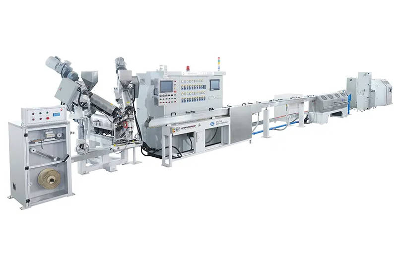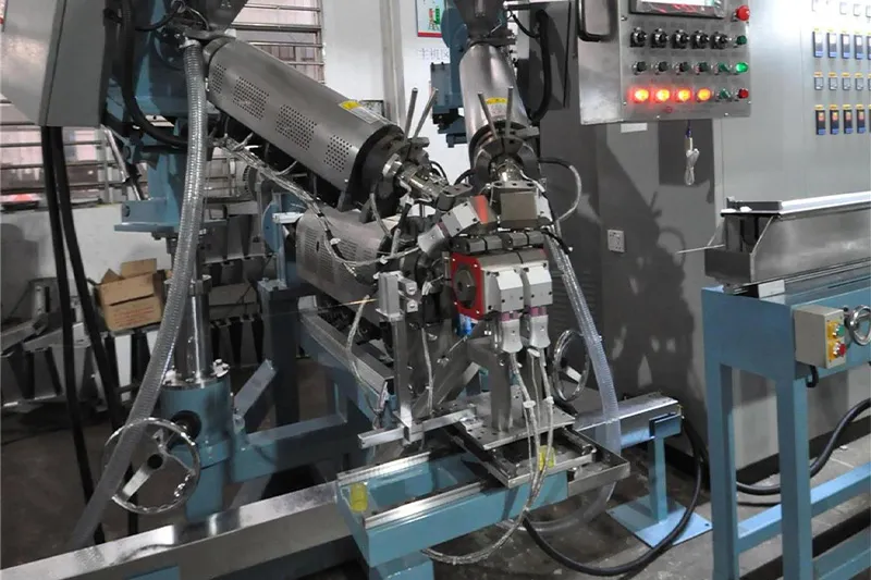
EV high voltage cable extrusion requires coordinated control of the conductor, insulation, shielding interface, outer jacket, crosslinking process and online inspection—not merely a larger conventional wire extruder.
A production line for automotive high voltage cable must be configured around the finished cable structure. Important inputs include conductor material, conductor cross-section, voltage class, insulation material, shielding design, jacket material, target outside diameter and applicable automotive specification.
The term “EV cable” also requires clarification. In-vehicle high voltage cables connecting the battery, inverter, motor, compressor or charging system are different from flexible charging cables used between charging equipment and the vehicle. Their structures, operating conditions and applicable specifications may differ.
This article follows the cable from the inside outward. At every stage, it explains what the product requires and which equipment function creates that result.
Manufacturers planning new automotive cable capacity can review QingFeng SFS EV cable extrusion line solutions for configurable insulation, jacketing and multi-layer extrusion systems.
Begin With the Cable Cross-Section
An EV high voltage cable is a layered engineering product. Depending on the application, it may contain:
- Copper or aluminum conductor
- Primary insulation
- Optional separator or wrapping layer
- Metallic shielding
- Optional shielding protection or binding tape
- Outer jacket
- Identification, printing and reel packaging
Not every product contains all seven layers. A simple unshielded battery cable may require conductor insulation only, while a screened motor cable may require insulation, shielding and an outer orange jacket.
This distinction determines whether the manufacturer needs:
- One insulation extrusion line
- Separate insulation and jacketing lines
- A multi-layer co-extrusion system
- Taping equipment
- Braiding or shielding equipment
- Irradiation equipment
- Additional spark testing and concentricity measurement
- A complete production cell rather than one standalone extruder
The finished cable construction should be frozen before the extrusion-line configuration is approved.
Typical EV Cable Structures
| Cable Type | Simplified Structure | Main Manufacturing Priority |
| Unshielded single-core cable | Conductor + insulation | Stable insulation thickness and high-voltage integrity |
| Shielded single-core cable | Conductor + insulation + shield + jacket | Concentric insulation, shield coverage and smooth jacketing |
| Shielded multi-core cable | Insulated cores + assembly + shield + jacket | Core geometry, shielding stability and controlled outer diameter |
| Flexible battery cable | Fine-stranded conductor + insulation or jacket | Low conductor tension and flexible material processing |
| Motor or inverter cable | Conductor/core assembly + shield + jacket | Electromagnetic shielding and thermal-mechanical durability |
| Charging cable | Multiple power, grounding and signal cores + fillers + jacket | Flexibility, core assembly, jacket durability and repeated handling |
Stage 1: Bring the Conductor Into the Line Without Changing It
The extrusion process begins before the polymer reaches the screw.
High voltage EV cables may use large copper conductors, fine-stranded flexible conductors or aluminum conductors. Each creates different payoff and tension requirements.
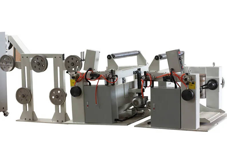
Payoff Requirements
The payoff system should be selected according to:
- Conductor cross-section
- Conductor material
- Solid or stranded construction
- Reel diameter and reel weight
- Maximum production speed
- Allowable conductor tension
- Frequency of reel changes
- Need for continuous production
Large conductors require sufficient reel-loading capacity and controlled braking. Fine-stranded conductors require smoother tension to prevent strand displacement, stretching or conductor deformation.
An unstable payoff can cause:
- Eccentric insulation
- Diameter variation
- Conductor elongation
- Surface marks
- Irregular conductor entry into the crosshead
- Cable movement during speed changes
Straightening and Preheating
A conductor straightener can improve entry stability before the extrusion crosshead. Preheating may also be used to remove surface moisture, stabilize conductor temperature or improve the interface between the conductor and insulation.
Preheating should remain adjustable. The correct setting depends on conductor size, plating, material formulation, line speed and required bonding behavior.
Excessive heat can affect the compound or create unwanted adhesion. Insufficient heat may contribute to moisture-related defects or unstable insulation contact.
Stage 2: Build the Electrical Insulation
The primary insulation separates the high-voltage conductor from surrounding components. Its integrity depends on both material properties and extrusion accuracy.
Common material families used in automotive cable production may include:
- Crosslinkable polyethylene compounds
- Thermoplastic elastomers
- Thermoplastic polyurethane
- Polyolefin-based compounds
- Fluoropolymers for specialized temperature environments
- Other automotive cable compounds developed for specific OEM requirements
The exact formulation matters more than the general material name.
Two compounds described as XLPE or TPU may have different:
- Drying requirements
- Processing temperatures
- Melt-flow behavior
- Crosslinking methods
- Shrinkage
- Adhesion
- Flame performance
- Abrasion resistance
- Temperature classification
Material-to-Equipment Relationship
| Material or Process Family | Main Production Concern | Equipment Requirement |
| Thermoplastic polyolefin | Output and dimensional stability | Stable screw design, cooling and haul-off synchronization |
| Crosslinkable PE compound | Controlled extrusion followed by crosslinking | Compatible screw profile and defined downstream crosslinking route |
| TPU | Moisture, shear and surface quality | Effective drying, stable feeding and controlled melt temperature |
| TPE or TPV | Elastic recovery and diameter stability | Precise cooling and line-speed control |
| Fluoropolymer | High processing temperature and residence time | High-temperature extruder and compatible material-contact components |
| Multi-layer construction | Layer balance and interface stability | Multiple extruders, co-extrusion crosshead and synchronized output |
The extruder should be sized for the stable operating output of the actual compound, not selected only by its maximum advertised capacity.
An oversized extruder may create excessive residence time during low-output production. An undersized extruder may need excessive screw speed, increasing shear and pressure variation.
Screw and Barrel Configuration
The screw must provide consistent feeding, melting and metering without damaging the compound.
Important specification points include:
- Screw diameter
- Length-to-diameter ratio
- Compression profile
- Motor and gearbox capacity
- Maximum and normal screw-speed range
- Barrel heating and cooling zones
- Melt-pressure measurement
- Material-contact construction
- Ease of cleaning
- Output range with the intended compound
A general-purpose screw may work during a brief trial but still perform poorly during long production runs. The equipment supplier should evaluate the material data sheet, target output and expected product range before finalizing the screw.
Stage 3: Decide Whether Crosslinking Is Part of the Route
Not every EV cable material requires a separate crosslinking step.
Thermoplastic materials normally solidify through cooling. Crosslinkable materials require an additional process that creates bonds between polymer chains.
Depending on the compound system, crosslinking may involve:
- Electron-beam irradiation
- Chemical or thermal processes
- Moisture-related curing systems
- Other material-specific methods
Electron-beam irradiation is used in wire and cable production to crosslink suitable polymer insulation and jackets. Extrusion and irradiation remain separate process stages: the cable must first be extruded within the correct geometry, then exposed to a controlled irradiation process.
When Irradiation Affects Line Planning
A manufacturer considering irradiated cable should define:
- Material formulation
- Cable diameter
- Required crosslinking level
- Production speed
- Number of beam passes
- Cable handling pattern
- Dose-control method
- Reel or continuous processing route
- Verification test after irradiation
Irradiation cannot correct poor extrusion.
If the insulation is eccentric, contaminated or dimensionally unstable before crosslinking, irradiation may lock those defects into the finished cable.
Crosslinking improves the polymer network, but dimensional quality must already be created during extrusion.
Stage 4: Prepare the Insulated Core for Shielding
Shielded EV cables require stable insulation geometry because the metallic shield is applied around the insulated core.
Common shielding structures may include:
- Copper wire braid
- Copper tape
- Aluminum-based tape
- Combined tape and braid
- Other OEM-defined shielding constructions
The extrusion line may not apply the metallic shield itself, but it must produce an insulated core suitable for the next process.
Why Insulation Geometry Matters to Shielding
An unstable core diameter can affect:
- Braid coverage
- Shielding density
- Tape overlap
- Material consumption
- Cable flexibility
- Final jacket thickness
- Finished cable diameter
The insulated core should therefore be checked before shielding for:
- Outside diameter
- Concentricity
- Surface quality
- Reel winding
- Insulation damage
- Ovality
- Cable tension history
Where a tape or separator is required before or after shielding, the production route may also include wrapping or taping equipment.
QingFeng SFS offers broader cable machinery for extrusion and supporting processes, allowing the production route to be considered as a connected system rather than an isolated extruder.
Stage 5: Apply the Outer Jacket Without Disturbing the Shield
After shielding, the cable may return to an extrusion line for outer jacketing.
The jacket protects the cable from mechanical damage, abrasion, fluids, temperature exposure and installation stress. In many EV applications, orange is used to identify high-voltage circuits.
The exact color, thickness and material requirements should follow the applicable vehicle standard and customer specification.
Jacketing Challenges
The incoming shielded cable is more complex than a bare conductor. It may have:
- A rough braided surface
- Tape overlaps
- Variable compressibility
- A non-circular profile
- Larger diameter
- Higher weight
- Greater bending stiffness
These conditions affect crosshead design, tooling, tension and jacket surface quality.
The jacketing line should control:
- Core payoff tension
- Shield integrity
- Jacket wall thickness
- Finished cable diameter
- Surface appearance
- Color consistency
- Printing position
- Cooling
- Take-up tension
Pressure or Tubing Extrusion
The tooling approach depends on whether the jacket must fit tightly around the underlying shield or form with controlled clearance.
The equipment supplier should review:
- Shield construction
- Cable core diameter
- Required adhesion
- Stripping requirements
- Material draw-down
- Surface profile
- Minimum jacket thickness
There is no universal die setting for every shielded EV cable. Tooling trials should use a representative shielded core rather than a smooth plastic rod.
Stage 6: Control the Cable While It Is Being Made
Automotive high voltage cable quality should be monitored continuously where practical.
Post-production sampling remains important, but it cannot economically detect every short-duration diameter change, conductor exposure or insulation defect.
Online Control Map
| Measurement | What It Reveals | Possible Line Response |
| Melt temperature | Material-processing stability | Adjust temperature profile or investigate shear |
| Melt pressure | Feeding, melting and flow stability | Inspect material feed, screens, screw or tooling |
| Outside diameter | Finished dimensional variation | Adjust screw or haul-off speed within approved limits |
| Concentricity | Position of conductor inside insulation | Adjust crosshead centering or conductor path |
| Wall thickness | Minimum insulation or jacket layer | Correct tooling, centering or output balance |
| Spark test | Discontinuities in insulation | Alarm, mark defect or stop line according to procedure |
| Surface inspection | Lumps, depressions and contamination | Identify tooling, material or cooling problem |
| Line speed | Production reference for other systems | Synchronize extrusion, testing and take-up |
| Conductor tension | Mechanical stability | Adjust payoff, accumulator or capstan |
| Capacitance where relevant | Electrical geometry of certain cables | Adjust extrusion geometry within approved process limits |
QingFeng SFS cable insulation and jacketing extrusion systems can be configured with PLC and HMI control, online measurement and material-specific extrusion functions.
Feedback Control Requires Limits
Automatic diameter correction can improve production stability, but feedback should not hide the root cause of a process problem.
For example, repeated speed correction may compensate temporarily for:
- Unstable material feeding
- Poor drying
- Melt-pressure fluctuation
- Slipping haul-off belts
- Irregular conductor tension
The control system should therefore record both the measurement and the corrective action.
Stage 7: Connect Production Data to the Finished Reel
EV cable manufacturers often need to associate each finished reel with its production inputs and process history.
A practical traceability record may include:
- Material supplier and batch
- Conductor batch
- Shielding material batch
- Product code
- Tooling combination
- Machine recipe
- Operator
- Production date and time
- Average and minimum wall thickness
- Diameter trend
- Spark-test result
- Alarm history
- Reel number
- Final inspection status
Recipe management should also control who can modify critical parameters.
Useful HMI functions include:
- User access levels
- Product recipes
- Parameter limits
- Alarm records
- Trend charts
- Production reports
- Maintenance reminders
- Data export
- Backup and recovery
Traceability does not replace process control, but it makes deviations easier to investigate and repeated production easier to compare.
Should You Use One Line or Several Production Cells?
The correct answer depends on cable structure, volume and material range.
| Configuration | Advantages | Limitations | Suitable Situation |
| One flexible extrusion line | Lower initial equipment count and easier use across products | More changeovers and possible contamination risk | Moderate volume and compatible material families |
| Separate insulation and jacketing lines | Independent process optimization and higher scheduling flexibility | More floor space and investment | Shielded cable with separate core and jacket stages |
| Multi-layer co-extrusion line | Layers applied in one pass with controlled interfaces | More complex crosshead and process balancing | Defined multi-layer insulation or jacket structure |
| Dedicated automotive cable line | Stable recipes and reduced material changeover | Less flexible for unrelated products | High-volume production of a narrow product family |
| Integrated production cell | Coordinated extrusion, inspection and downstream handling | Requires detailed project engineering | New factory or complete EV cable production project |
A line intended to process both small insulated cores and large shielded jackets may require very broad operating capability. In some factories, two correctly sized lines provide more stable production than one highly compromised line.
Defects Reveal Which Part of the Line Is Unstable
| Observed Defect | Likely Causes | Equipment Areas to Investigate |
| Diameter fluctuation | Unstable feeding, melt pressure or haul-off speed | Hopper, screw, pressure sensor, capstan and feedback control |
| Eccentric insulation | Conductor movement or incorrect crosshead centering | Payoff, straightener, tip, die and crosshead adjustment |
| Bubbles | Wet material, contamination or overheating | Dryer, feeding path and temperature profile |
| Black spots | Material degradation or dead zones | Screw, barrel, adapter, crosshead and cleaning procedure |
| Rough surface | Incorrect melt condition or excessive shear | Material drying, screw design and die temperature |
| Jacket marks | Shield irregularity or poor tooling | Incoming core, tape overlap, braid and jacket die |
| Cable flattening | Insufficient cooling or excessive capstan pressure | Cooling trough, guide system and haul-off |
| Spark faults | Thin wall, contamination or conductor exposure | Crosshead alignment, material cleanliness and conductor path |
| Reel deformation | Excessive take-up tension | Capstan, accumulator, traverse and take-up |
| Color variation | Poor mixing, contamination or unstable feed | Material preparation, dosing and screw |
The most effective troubleshooting sequence is to separate the process into three zones:
- Material delivery
- Extrusion and tooling
- Downstream cable handling
Changing several settings at the same time makes the actual cause harder to identify.
Build the RFQ Around the Cable, Not the Machine Model
A useful request for quotation should include the following information.
Cable Definition
- Application inside the vehicle
- Applicable standard or customer specification
- Voltage class
- Shielded or unshielded structure
- Single-core or multi-core construction
- Finished cable drawing
Conductor Information
- Copper or aluminum
- Solid or stranded
- Cross-section range
- Minimum bending sensitivity
- Reel dimensions and weight
Extrusion Materials
- Exact compound grade
- Insulation and jacket materials
- Material data sheets
- Drying requirement
- Crosslinking method
- Color and additive information
Dimensional Requirements
- Conductor diameter
- Insulation thickness
- Insulated-core diameter
- Shielded-core diameter
- Jacket thickness
- Finished cable diameter
- Concentricity or minimum-wall requirement
Production Requirements
- Target line speed
- Required output
- Annual production volume
- Product change frequency
- Factory voltage
- Available floor space
- Required operator count
Quality-Control Requirements
- Laser diameter measurement
- Wall-thickness measurement
- Concentricity measurement
- Spark testing
- Surface inspection
- Printing
- Data recording
- Automatic feedback
- Reel identification
A detailed cable drawing and material specification are more useful to an equipment supplier than a request for a “standard EV cable machine.”
Factory Acceptance Testing Should Follow the Real Production Route
The factory acceptance test should use the intended or representative conductor, compound, tooling and reel configuration.
Recommended test stages include:
- Confirm material preparation and drying
- Verify conductor payoff and tension
- Record temperature and melt-pressure stability
- Measure insulation or jacket diameter
- Verify minimum wall thickness and concentricity
- Inspect the cable surface
- Test spark-test operation
- Review startup scrap
- Test acceleration and deceleration
- Inspect reel winding
- Retrieve production and alarm data
- Demonstrate cleaning and tooling changeover
The test should include the product that presents the greatest manufacturing challenge, such as:
- Smallest conductor
- Largest conductor
- Thinnest wall
- Highest output
- Lowest output
- Softest material
- Highest processing temperature
- Most demanding concentricity
A line that runs an easy demonstration product does not necessarily prove that it can manufacture the actual cable.
Conclusion
EV high voltage cable production is a sequence of connected manufacturing stages.
The payoff protects the conductor. The first extrusion stage creates electrical insulation. Taping or shielding builds electromagnetic protection. The next extrusion stage forms the protective jacket. Irradiation may crosslink compatible materials. Online inspection verifies that the cable remains within the approved process window.
The most suitable EV cable production line is the one that repeatedly manufactures the specified cable structure—not simply the line with the largest extruder or highest stated speed.
Before selecting equipment, define the complete cable cross-section, material grades, crosslinking route, shielding process, dimensional tolerances and inspection plan.
QingFeng SFS can help manufacturers configure an automotive high voltage cable extrusion project around actual product drawings, material specifications and production targets.
Frequently Asked Questions
What equipment is needed for EV high voltage cable extrusion?
A typical production route may require conductor payoff, preheating, an insulation extruder, crosshead, cooling trough, diameter measurement, spark testing, capstan and take-up. Shielded cables may also require taping, braiding and a separate jacket extrusion line.
Which materials are commonly used for automotive high voltage cable insulation?
Material selection may include crosslinkable polyethylene compounds, thermoplastic elastomers, TPU, polyolefin-based compounds and specialized fluoropolymers. The correct choice depends on temperature, flexibility, abrasion, electrical and customer requirements.
Does every EV cable production line need irradiation equipment?
No. Irradiation is used only when the selected compound and product specification require radiation crosslinking. Conventional thermoplastic insulation and jackets normally do not require this stage.
Why is concentricity important in high voltage cable extrusion?
Concentricity helps maintain the required minimum insulation wall around the conductor. A cable can have the correct outside diameter while still having an excessively thin wall on one side.
Can insulation and outer jacketing be produced on the same extrusion line?
It may be possible when material, diameter and output ranges are compatible. However, separate lines often provide greater flexibility for shielded cables because insulation and jacketing occur at different stages.
What is the difference between an automotive high voltage cable and an EV charging cable?
Automotive high voltage cables are installed inside the vehicle and connect high-voltage components. Charging cables connect the vehicle to external charging equipment and often contain multiple power, grounding, communication and control cores.
Why are many automotive high voltage cables orange?
Orange is commonly used to identify high-voltage circuits and is required in certain regulatory contexts for high-voltage cables outside protective enclosures. The final color requirement should follow the target market and customer specification.
What information is required to quote an EV cable production line?
The supplier needs the cable drawing, conductor range, material grades, insulation and jacket thicknesses, shielding structure, target speed, reel sizes, online inspection requirements and factory conditions.