Mica taping improves fire-resistant cable performance by creating a heat-stable electrical insulation barrier around the conductor. When ordinary polymer insulation softens, decomposes or burns away, the mica layer helps keep conductors electrically separated so the circuit can continue operating for a specified period under defined fire-test conditions.
This is why mica tape is widely used in cables serving emergency power, fire alarms, smoke-control systems, evacuation systems, pumps, lighting, industrial safety circuits and other applications where electrical continuity may be required during a fire.
However, adding mica tape does not automatically create a compliant fire-resistant cable.
The final result depends on:
- The type and construction of the mica tape
- Tape width and thickness
- Number of wrapping layers
- Overlap between adjacent turns
- Tape tension
- Conductor surface condition
- Wrapping direction
- Insulation and sheath materials
- Cable assembly
- The applicable circuit-integrity test
Fire resistance is a property of the complete cable system, while mica taping creates one of its most important protective layers.
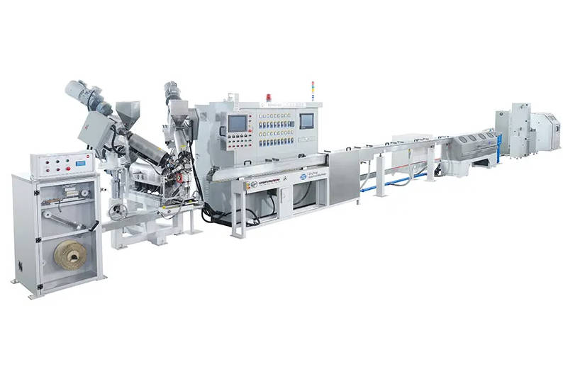
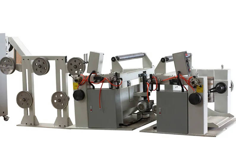
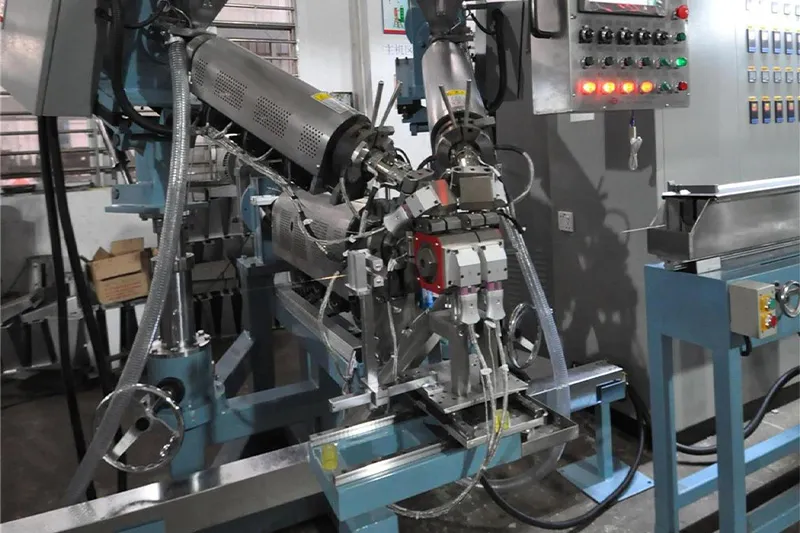
Cable manufacturers developing this process can review QingFeng SFS mica and fire-resistant cable taping equipment for configurable single-layer, multi-layer and tension-controlled wrapping systems.
First, Separate Fire Resistance From Flame Retardancy
Fire-resistant cable and flame-retardant cable are often discussed as though they provide the same protection. They address different performance questions.
IEC 60331 test methods assess whether specified cables maintain circuit integrity while exposed to fire and, in some methods, mechanical shock. IEC 60332 evaluates resistance to flame propagation on individual or bunched cables. A cable can therefore resist the spread of flame without necessarily continuing to transmit power or signals during the fire.
| Cable Performance | Main Question | Primary Design Focus |
| Flame retardancy | How far does flame spread along the cable? | Combustion behavior of insulation and sheath compounds |
| Circuit integrity | Does the electrical circuit continue operating during fire exposure? | Continued separation and insulation of energized conductors |
| Low smoke | How much smoke is generated? | Combustion products of the cable materials |
| Halogen-free construction | Do the materials avoid halogen-containing compounds? | Material formulation throughout the cable |
| Fire resistance with mechanical shock | Can the cable maintain the circuit while exposed to heat and impact? | Electrical insulation plus structural stability |
Mica taping primarily supports circuit integrity. It does not replace the need to select appropriate insulation, bedding, filler and sheath materials for the complete cable specification.
Different parts of the IEC 60331 series apply to different cable constructions, voltage ranges and test arrangements. For example, IEC 60331-4:2024 addresses certain power cables rated above 0.6/1.0 kV and up to 18/30 kV under specified fire and mechanical-shock conditions. The correct target standard should therefore be confirmed before the cable structure and wrapping process are finalized.
What Happens to a Cable During Fire Exposure?
The value of mica is easier to understand when the cable is examined as a sequence of protective layers.
Stage 1: The Cable Operates Under Normal Conditions
Before a fire, the polymer insulation around the conductor performs most of the everyday electrical and mechanical work.
Depending on the product, the polymer layers may provide:
- Electrical insulation
- Flexibility
- Abrasion resistance
- Moisture protection
- Chemical resistance
- Mechanical separation
- Color identification
- A smooth surface for cable assembly
The mica tape remains beneath the insulation or other cable layers. During normal operation, it is not intended to replace the polymer insulation.
Its importance becomes greater as the temperature rises.
Stage 2: Heat Begins to Damage the Polymer Layers
As the cable is exposed to fire, the sheath and insulation may soften, shrink, crack, carbonize or separate from the conductor. The exact behavior depends on the material formulation and cable design.
At this point, several risks appear:
- Two conductors may move closer together
- The conductor may contact a metallic shield or enclosure
- Carbonized material may create a conductive path
- Mechanical shock may disturb the cable structure
- Insulation thickness may no longer be maintained
- The original cable geometry may collapse
A flame-retardant compound may help limit flame propagation, but that does not necessarily mean it can continue acting as the primary electrical insulation throughout the circuit-integrity test.
Stage 3: The Mica Layer Becomes the Main Electrical Barrier
Mica is valued in fire-resistant cable construction because it maintains electrical insulating capability under severe heat exposure. Mica tapes for fire-resistant cables are commonly made from mica paper combined with a reinforcing backing and heat-resistant binder. Depending on the product, the reinforcement may include glass fabric or a polymer film.
As the surrounding polymer loses its original form, the wrapped mica layer helps:
- Keep the conductor electrically separated
- Reduce the risk of conductor-to-conductor contact
- Reduce the risk of conductor-to-shield contact
- Maintain an insulation path around the conductor
- Support circuit continuity for the specified test period
The mica layer does not need to remain visually unchanged; it needs to remain sufficiently continuous and electrically effective.
This distinction is important. During fire exposure, the tape backing or binder may change, but the mineral insulation layer must remain positioned around the conductor without opening a direct electrical fault path.
Stage 4: Mechanical Movement Tests the Weakest Areas
Heat is not the only threat to the mica layer.
Fire-resistant cable tests or real installations may also expose the cable to:
- Mechanical shock
- Vibration
- Thermal expansion
- Conductor movement
- Falling debris
- Distortion of cable supports
- Shrinkage of surrounding polymer layers
This is where small manufacturing defects become important.
A narrow gap, cracked tape edge or weak transition may not cause an electrical problem during ordinary operation. Once the cable is heated and mechanically disturbed, that local defect may become the point where circuit integrity is lost.
The Mica Layer Works Only When Coverage Is Continuous
The insulation path around the conductor can be weakened by several wrapping defects.
| Wrapping Defect | What Happens During Production | Possible Effect During Fire Exposure |
| Insufficient overlap | Adjacent tape turns do not provide enough coverage | Heat or movement may open a direct gap |
| Tape break | Wrapping stops temporarily or reconnects poorly | A section of conductor may have incomplete protection |
| Cracked mica paper | Tape appears wrapped but contains local fractures | Mechanical movement may enlarge the damaged area |
| Folded tape edge | Tape thickness becomes irregular | Weak coverage and uneven subsequent insulation |
| Loose wrapping | Tape can shift before extrusion or assembly | Gaps may form as surrounding layers soften |
| Excessive tension | Tape stretches, narrows or cracks | Overlap and insulation continuity are reduced |
| Misaligned second layer | Weak areas in two layers coincide | Additional tape does not provide effective redundancy |
| Poor start or joint | Local tape transition is not controlled | Creates a concentrated weak point |
The performance contribution of mica depends less on the presence of tape than on the absence of an uninterrupted weak path through the wrapped layer.
Overlap Converts a Spiral Tape Into a Continuous Barrier
Mica tape is generally wrapped helically around the conductor. Because one strip cannot cover a long cable in a straight direction, each turn partially covers the preceding turn.
This overlap performs several functions:
- Closes the spiral path between adjacent turns
- Compensates for small tape-width variations
- Provides additional coverage when the cable bends
- Reduces the effect of minor positioning errors
- Creates more than one thickness of mica over much of the conductor
What Happens When Overlap Is Too Low?
Low overlap can reduce tape consumption and increase production speed, but it also leaves less tolerance for process variation.
A small change in any of the following may create a gap:
- Cable speed
- Taping-head speed
- Tape width
- Tape tension
- Wrapping angle
- Conductor diameter
- Cable centering
What Happens When Overlap Is Excessive?
More overlap does not always produce a proportionally better cable.
Excessive overlap may:
- Increase tape consumption
- Increase cable diameter
- Create a less uniform surface
- Reduce flexibility
- Increase material cost
- Slow production
- Make later extrusion more difficult
- Produce local thickness variation
The overlap should therefore be defined by the cable design, tape properties and validation results rather than by a general assumption that more material always means better fire resistance.
Tape Tension Decides Whether the Layer Is Stable or Damaged
Mica tape is more sensitive to handling than many ordinary polyester or non-woven tapes.
The machine must keep the tape tight enough to follow the conductor while avoiding enough force to damage the mica paper or reinforcement.
When Tension Is Too High
Excessive tension may cause:
- Tape breakage
- Microscopic or visible cracking
- Narrowing of the tape
- Reduced overlap
- Edge damage
- Deformation of fine conductors
- Frequent machine stops
When Tension Is Too Low
Insufficient tension may cause:
- Wrinkles
- Loose tape
- Layer movement
- Folded edges
- Unstable cable diameter
- Poor entry into the extrusion crosshead
- Tape displacement during reel handling
The challenge becomes greater as the tape roll is consumed. A full tape roll has a different diameter and rotational inertia from a nearly empty roll.
A basic braking system may therefore apply different tension at the beginning and end of the tape package.
QingFeng SFS taping equipment can be configured with dynamic dancers, load-cell tension measurement, torque-feedback control and automatic compensation as tape packages change from full to empty. The available line configurations also include multiple synchronized taping heads, tape-break detection and inline inspection options. (dgqfmachine.com)
Why Fire-Resistant Cables Often Use More Than One Mica Layer
A second mica layer can provide redundancy.
If the first layer contains a small gap or damaged edge, the second layer may cover that location. This benefit depends on how the layers are applied.
| Layer Arrangement | Potential Benefit | Main Process Risk |
| One mica layer | Lower cost and smaller cable diameter | Less redundancy against a local defect |
| Two layers in the same direction | Additional mica thickness | Gaps may follow similar spiral paths |
| Two layers in opposite directions | Crosses the spiral paths of the two layers | Requires independent head and tension control |
| Layers applied in separate passes | Each layer can be inspected independently | More handling and production time |
| Two layers applied inline | Higher production efficiency | More demanding synchronization |
Opposite-direction wrapping is often considered because the second spiral crosses the first, making it less likely that weak paths align continuously along the conductor.
However, the second layer should not simply duplicate the settings of the first. The required tension, forming point and overlap may differ according to the tape and conductor structure.
A second mica layer improves redundancy only when it covers the weaknesses of the first layer instead of reproducing them.
Mica Type Influences Both Fire Performance and Machine Settings
Mica tape is not one uniform material.
Cable manufacturers may evaluate:
- Phlogopite mica tape
- Muscovite mica tape
- Synthetic mica tape
- Glass-fabric-backed tape
- Film-backed tape
- Single-sided or multi-layer reinforcement
- Different binders and mica contents
The correct selection depends on the target cable, test conditions, flexibility, tensile strength, tape dimensions and downstream processing.
Material Differences That Affect Taping
| Tape Property | Effect on Cable Design | Effect on the Taping Process |
| Tape thickness | Changes insulation build and finished diameter | Affects overlap, head speed and forming angle |
| Tensile strength | Influences handling and break resistance | Determines the usable tension range |
| Flexibility | Influences wrapping around small conductors | Affects minimum bending and wrinkle risk |
| Backing material | Adds mechanical support | Changes friction and tape guidance |
| Tape width | Changes coverage and material consumption | Changes pitch and rotational-speed requirements |
| Binder system | Influences tape cohesion | May affect dust, heat response and processing |
| Roll construction | Determines continuous running length | Changes rotating inertia and tension behavior |
A machine trial using a different mica tape from the intended production material can produce misleading results.
Even when two tapes have the same nominal width and thickness, their backing friction, brittleness and roll quality may be different.
Mica Taping Must Survive the Next Production Stages
The wrapping process is not complete when the tape leaves the taping head.
The wrapped conductor may still pass through:
- Accumulators
- Guide wheels
- Payoff and take-up systems
- Insulation extrusion
- Core assembly
- Cabling
- Filling
- Additional taping
- Armoring
- Sheath extrusion
Each stage can disturb the mica layer.
Risks Between Taping and Extrusion
A correctly wrapped conductor may be damaged by:
- Excessive take-up tension
- Tight reel diameter
- Tape movement during reel transfer
- Guide wheels with sharp edges
- Abrupt payoff braking
- Dust or moisture contamination
- Excessive crosshead pressure
- Poor centering during extrusion
For this reason, the mica wrapping machine should be evaluated as part of a connected fire-resistant cable manufacturing process.
A complete fire-resistant cable taping system may include conductor payoff, straightening, one or more taping heads, tension monitoring, compacting, tape-break detection, pulling and take-up equipment.
Inline integration with the next production stage may reduce intermediate handling, but it also requires more accurate synchronization between the taping and extrusion sections.
Turning Cable Performance Requirements Into Machine Functions
The cable specification should be translated into measurable machine requirements.
| Cable Requirement | Necessary Process Control | Relevant Machine Function |
| Continuous mica coverage | Stable pitch and overlap | Synchronized head and line-speed control |
| Tape without cracks | Controlled low tension | Dancer, torque control or load-cell feedback |
| Multiple protective layers | Independent layer control | Dual or multi-head taping system |
| Stable wrapped diameter | Consistent tape angle and compaction | Adjustable forming point and compacting unit |
| No missed tape section | Rapid fault response | Tape-break detection and line alarm |
| Stable coverage during speed changes | Coordinated acceleration | PLC recipes and synchronized drives |
| Traceable production | Recorded process data | HMI recipes, alarm records and reports |
| Smooth transfer to extrusion | Controlled take-up and payoff | Coordinated reel tension and cable handling |
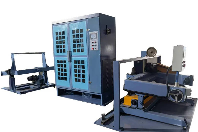
QingFeng SFS provides wire and cable taping machines in horizontal, vertical and multi-layer configurations. The systems can be adapted for mica tape and other high-temperature materials, with optional tension control, multiple taping units, heating, compacting and inline inspection functions. (dgqfmachine.com)
Process Verification Should Start Before the Fire Test
A final fire test gives a pass-or-fail result, but it may not clearly identify where a manufacturing problem began.
Cable manufacturers should therefore establish process checks before the completed cable reaches the fire-test laboratory.
Incoming Tape Inspection
Check:
- Material identification
- Batch number
- Tape width
- Tape thickness
- Roll condition
- Visible edge damage
- Splices or joints
- Storage condition
Startup Approval
Check:
- Correct wrapping direction
- Overlap
- Tape tension
- Number of layers
- Surface wrinkles
- Conductor centering
- Tape forming point
Online Monitoring
Monitor:
- Taping-head speed
- Cable speed
- Tension
- Tape break
- Cable break
- Equipment alarms
- Production length
Offline Inspection
Inspect samples for:
- Actual overlap
- Layer continuity
- Tape damage
- Wrapped diameter
- Surface uniformity
- Layer alignment
- Tape adhesion or stability
Finished-Cable Validation
Depending on the product specification, testing may include:
- Electrical resistance
- Voltage withstand
- Insulation resistance
- Mechanical tests
- Flame-propagation tests
- Circuit-integrity tests
- Tests involving mechanical shock or other specified conditions
This creates a quality chain connecting the mica tape batch, machine recipe, production reel and final cable test.
Common Misunderstandings About Mica-Taped Cable
“A Thicker Mica Layer Always Gives Better Fire Resistance”
A thicker layer may improve protection in some designs, but it can also increase diameter, stiffness and process instability. The full cable structure must be validated.
“If the HMI Shows the Correct Overlap, Coverage Is Correct”
Displayed overlap is often calculated from machine speed and tape dimensions. Actual coverage can still change because of tape stretching, slipping or conductor movement.
“Two Layers Automatically Eliminate Gaps”
Two layers help only when their tension, direction and alignment are controlled. Two poorly applied layers can still contain aligned weak areas.
“Flame-Retardant Insulation Makes Mica Unnecessary”
Flame-retardant compounds and mica layers perform different functions. One primarily controls combustion behavior; the other helps preserve electrical insulation after polymer layers are damaged.
“The Highest Taping Speed Produces the Lowest Cable Cost”
Usable output depends on tape-break frequency, startup scrap, overlap stability and fire-test yield. A slower stable process may produce more acceptable cable than a high-speed process with repeated defects.
How to Evaluate a Mica Taping Process
A practical evaluation should include the actual conductor and mica tape.
Do not test only with a smooth substitute tape that is easier to process.
The production trial should verify:
- Tape installation and threading
- Stable wrapping at low speed
- Correct overlap and direction
- Tape tension with a full roll
- Operation at the target line speed
- Acceleration and deceleration
- Tape-break response
- Tension with a partly consumed roll
- Simultaneous operation of multiple heads
- Surface quality of each layer
- Wrapped conductor take-up
- Transfer into the next cable process
The most demanding cable condition should be included, such as:
- The smallest conductor
- The most brittle tape
- The widest tape
- The highest required overlap
- The lowest permissible tension
- Opposite-direction double wrapping
- The highest target production speed
Conclusion
Mica taping improves fire-resistant cable performance by preserving electrical separation after ordinary insulation layers begin to lose their protective function.
Its contribution depends on a clear chain of cause and effect:
- Mica provides heat-stable electrical insulation
- Spiral wrapping places the material around the conductor
- Overlap closes the path between tape turns
- Tension keeps the layer stable without damaging it
- Multiple layers provide redundancy
- Controlled downstream handling keeps the layer in place
- Fire testing validates the complete cable construction
A fire-resistant cable does not pass because it contains mica tape; it passes because the mica layer remains continuous and electrically effective throughout the specified fire exposure.
Manufacturers can explore QingFeng SFS mica taping machine configurations or review its broader wire and cable equipment capabilities when planning a complete fire-resistant cable production process.
Frequently Asked Questions
How does mica tape make a cable fire resistant?
Mica tape forms a heat-stable electrical insulation layer around the conductor. When polymer insulation is damaged by fire, the mica layer helps prevent electrical contact between conductors or other metallic components.
Is mica tape the same as flame-retardant cable insulation?
No. Flame-retardant insulation is designed mainly to limit combustion or flame spread. Mica tape is commonly used to help maintain electrical circuit integrity after ordinary insulation has been damaged.
Why is mica tape overlapped on fire-resistant cables?
Overlap prevents a direct spiral gap between adjacent tape turns. It also provides tolerance for small variations in tape position, conductor diameter and cable movement.
How many mica tape layers are required for a fire-resistant cable?
The required number depends on the tape, conductor size, cable structure and target test standard. Some constructions use one layer, while others use two or more layers for additional coverage.
Is opposite-direction mica taping better?
Opposite-direction layers can provide improved cross-coverage because the second spiral crosses the first. The benefit still depends on correct tension, overlap and alignment.
What causes mica tape to break during cable production?
Common causes include excessive tension, abrupt acceleration, sharp guides, poor roll condition, excessive rotating inertia and unsuitable tape-path alignment.
Does more mica tape always improve circuit integrity?
Not necessarily. Excessive tape can increase cable diameter, stiffness and surface irregularity. The layer design should be validated as part of the complete cable construction.
What machine controls are important for mica taping?
Important controls include tape tension, taping-head speed, cable speed, overlap, wrapping direction, tape-break detection and synchronization between multiple taping heads.
Can mica taping be completed inline with cable extrusion?
Yes. Inline production can reduce reel handling and layer movement, but the taping machine and extrusion line must be accurately synchronized.