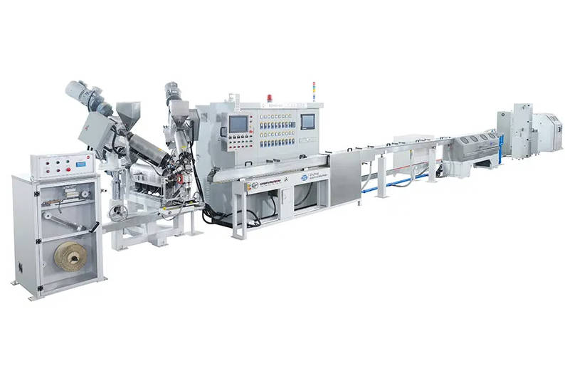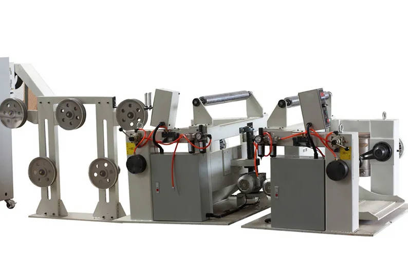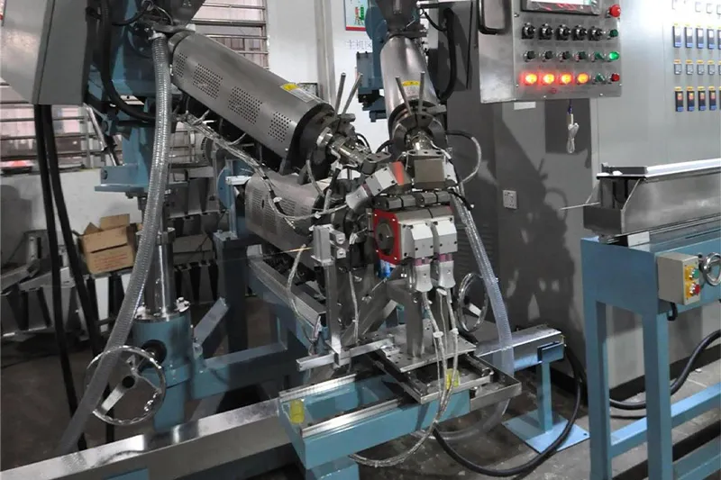
An insulating core wire extrusion line applies a controlled polymer insulation layer around a conductor while maintaining conductor tension, insulation thickness, concentricity, surface quality and finished wire diameter throughout continuous production.
The extrusion machine is only one station in this process.
A stable core wire production line normally depends on the coordination of:
- Conductor payoff
- Tension control
- Straightening or preheating
- Material feeding
- Extrusion
- Crosshead and tooling
- Cooling
- Online inspection
- Pulling
- Take-up
A problem at any one of these stages can appear later as uneven wall thickness, unstable diameter, rough surface, conductor eccentricity or excessive scrap.
This article therefore does not treat a core wire extrusion line as a standalone extruder. Instead, it follows one conductor from the incoming reel to the finished insulated core and explains what each production station must accomplish.
Manufacturers evaluating new insulation capacity can review QingFeng SFS cable extrusion line solutions for different materials, cable structures and production requirements.
Station 1: The Process Begins Before the Conductor Reaches the Extruder
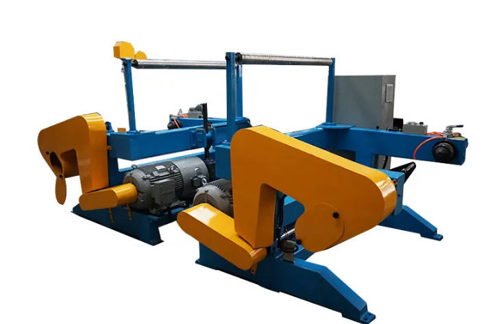
The first quality decision happens at the payoff.
If the conductor enters the extrusion crosshead with unstable tension or lateral movement, even a precise extruder can struggle to maintain a centered insulation layer.
The payoff system therefore needs to match:
- Conductor diameter
- Copper, aluminum or other conductor material
- Solid or stranded construction
- Input reel dimensions
- Reel weight
- Required line speed
- Allowable conductor tension
Why Conductor Tension Matters
Too much tension can:
- Stretch fine wire
- Alter conductor dimensions
- Damage delicate stranded conductors
- Increase wire-break risk
Too little or fluctuating tension can:
- Make the conductor move inside the crosshead
- Reduce insulation concentricity
- Create unstable outside diameter
- Produce problems during acceleration and deceleration
Insulation concentricity begins with a stable conductor path, not at the die exit.
For fine electronic or communication cores, low and stable tension can be more important than simply increasing maximum line speed.
Station 2: Straightening and Preheating Prepare the Conductor
The conductor should approach the extrusion crosshead in a repeatable condition.
Depending on the cable and material, the production route may include straightening and preheating.
What Straightening Does
Wire coming from a reel naturally carries curvature.
If this curvature remains excessive, the conductor may move laterally while entering the tooling.
Straightening helps create a more stable centerline before extrusion.
What Preheating Can Do
Conductor preheating may help:
- Remove surface moisture
- Stabilize conductor temperature
- Improve the conductor/polymer interface
- Reduce sudden cooling of the polymer around the conductor
However, more heat is not automatically better.
The suitable temperature depends on:
- Conductor size
- Line speed
- Insulation material
- Required adhesion
- Cable construction
Excessive preheating can create unwanted adhesion or affect the polymer process.
The system should therefore provide adjustable and repeatable control rather than one fixed temperature.
Station 3: Material Preparation Determines What Enters the Screw
The insulation polymer must reach the extruder in a stable condition.
Different cable products may use materials such as:
- PVC
- PE
- HDPE
- PP
- PU
- TPE-based compounds
- Foamed materials
- Other cable insulation compounds
QingFeng SFS wire and cable extrusion equipment can be configured for different insulation and extrusion materials.
The exact resin grade still matters.
Two materials from the same general polymer family can have different:
- Melt flow
- Processing temperature
- Moisture sensitivity
- Shrinkage
- Cooling behavior
- Surface characteristics
Drying Is Material-Dependent
Some materials are more sensitive to moisture than others.
If a moisture-sensitive compound enters extrusion without suitable preparation, possible defects include:
- Bubbles
- Rough surfaces
- Voids
- Unstable appearance
- Mechanical-property variation
The extrusion-line specification should therefore consider material preparation together with the extruder.
A supplier should know the actual material grade before the final screw and processing configuration is confirmed.
Station 4: The Extruder Must Create a Stable Melt, Not Just Melt Plastic
Inside the extruder, the material moves through several stages:
- Feeding
- Heating
- Melting
- Mixing
- Pressure development
- Metering
- Delivery to the crosshead
A useful extrusion process must deliver polymer at a stable temperature and pressure.
The purpose of the extruder is not simply to reach a high temperature or output—it is to deliver a consistent melt to the crosshead.
What Determines Extruder Size?
Important inputs include:
- Conductor range
- Finished wire diameter
- Insulation thickness
- Polymer type
- Target output
- Production speed
- Product range
An oversized extruder is not automatically an advantage.
If a large extruder operates continuously at very low output, material residence time may increase and small-wire production may become harder to stabilize.
An undersized machine creates the opposite problem: the screw may need to operate near its upper range to meet production demand.
The correct machine should operate comfortably within the expected production window.
Station 5: Screw Design Connects Material Behavior With Output
The screw affects:
- Feeding
- Melting
- Mixing
- Shear
- Residence time
- Pressure stability
- Output consistency
This is why a screw optimized for one material should not automatically be assumed suitable for every cable polymer.
The correct screw configuration depends on the material and product range.
Material and Process Relationship
| Material Requirement | Main Process Concern | Equipment Focus |
| Conventional insulation compound | Stable melting and output | Appropriate screw and temperature profile |
| Moisture-sensitive material | Bubbles and surface quality | Drying + controlled feeding |
| Soft or flexible compound | Pressure and surface stability | Screw shear and cooling control |
| Foamed material | Cell formation and dimensional stability | Material/process-specific screw and pressure control |
| High-precision thin insulation | Small output variation | Stable metering and accurate crosshead |
A machine should therefore be evaluated with the intended material, not only with an easier substitute during testing.
Station 6: The Crosshead Creates the Actual Insulation Geometry
The crosshead is where the conductor and molten polymer finally meet.
The conductor passes through the center while the polymer flows around it.
The crosshead and tooling strongly influence:
- Wall thickness
- Concentricity
- Surface finish
- Melt pressure
- Material flow
- Finished outside diameter
Tip and Die Selection
The tooling needs to match:
- Conductor diameter
- Finished diameter
- Insulation thickness
- Material behavior
- Extrusion method
Using unsuitable tooling can create:
- Excessive melt pressure
- Poor centering
- Rough surfaces
- Unstable dimensions
- Excessive material consumption
For factories producing many wire sizes, tooling management becomes part of production efficiency.
A clear product-to-tooling schedule can reduce setup errors and changeover time.
Station 7: Concentricity Is Created Here—but Controlled by the Whole Line
A finished wire may have the correct outside diameter and still have poor insulation geometry.
Imagine:
- Finished OD is correct
- Insulation is thick on the top side
- Insulation is thin on the bottom side
The overall diameter passes inspection, but the minimum wall may not.
That is a concentricity problem.
Possible causes include:
- Poor crosshead centering
- Conductor movement
- Unstable payoff tension
- Incorrect tip/die alignment
- Tool wear
- Cable vibration
Outside diameter alone does not prove that insulation wall thickness is uniform around the conductor.
For products where minimum insulation wall is important, concentricity should be considered independently from total diameter.
Station 8: Cooling Locks the Extruded Geometry Into the Finished Wire
The polymer leaving the die is still hot and mechanically soft.
Its final geometry continues changing during cooling.
Cooling affects:
- Shrinkage
- Surface appearance
- Finished diameter
- Roundness
- Mechanical stability
- Downstream handling
A typical line may use one or more cooling trough sections according to the cable and material.
Cooling Too Aggressively
Possible effects include:
- Surface stress
- Uneven solidification
- Dimensional change
- Product-specific surface problems
Cooling Too Slowly
Possible effects include:
- Cable deformation
- Guide marks
- Flattening
- Longer required cooling distance
- Problems entering the capstan
The cooling section therefore needs to match material, wall thickness and line speed.
Increasing production speed may require more than a faster extruder—it may also require additional cooling capability.
Station 9: Online Inspection Changes the Line From “Making Wire” to “Controlling Wire”
A basic extrusion line can produce insulated wire.
A more controlled line measures the product while it is being produced.
Possible online measurements include:
- Outside diameter
- Wall thickness
- Concentricity
- Surface condition
- Electrical insulation faults
- Line speed
QingFeng SFS extrusion systems support configurable PLC/HMI control and online inspection functions for production monitoring and dimensional quality control.
Why Online Diameter Measurement Matters
Without online measurement, the factory may discover a diameter problem only after producing a significant length of cable.
Real-time measurement allows operators to see trends earlier.
However, measurement itself does not solve the defect.
Diameter variation may still originate from:
- Unstable material feeding
- Melt-pressure fluctuation
- Screw-speed variation
- Puller-speed variation
- Changing conductor tension
The measurement tells the operator what is happening.
Process data helps explain why.
Station 10: Spark Testing Looks for What Diameter Measurement Cannot See
A cable may have the correct diameter and still contain an electrical insulation defect.
Possible faults include:
- Pinholes
- Local thin spots
- Exposed conductor
- Surface damage
For applicable cable products, spark testing provides an additional quality-control step.
The test system should work together with:
- Line speed
- Alarm logic
- Fault counting
- Production records
The appropriate test conditions depend on the cable specification.
The important purchasing question is not simply whether a line “has a spark tester,” but how the testing function fits the factory’s actual product requirements.
Station 11: The Capstan Controls More Than Line Speed
The capstan or pulling unit moves the cable through the production line.
Its speed interacts directly with extrusion output.
If polymer output remains constant but the cable moves faster:
- Insulation becomes thinner
- Finished diameter decreases
If the cable slows:
- More polymer is applied per unit length
- Insulation becomes thicker
- Finished diameter increases
This makes screw output and pulling speed a connected control pair.
Puller Slip Can Create Hidden Variation
Even when the control system displays a stable speed, actual cable movement can vary if the pulling mechanism slips.
Potential effects include:
- Diameter variation
- Unstable wall thickness
- Changing tension
- Poor take-up
The puller must therefore maintain stable grip without damaging soft insulation.
Station 12: Take-Up Determines Whether Good Wire Remains Good
The extrusion process is almost finished—but poor reel winding can still damage the product.
Take-up should control:
- Reel speed
- Cable tension
- Traverse
- Reel alignment
- Finished package shape
Excessive take-up tension can:
- Stretch small wire
- Deform soft insulation
- Change finished geometry
Insufficient tension can:
- Create loose reels
- Produce poor winding
- Cause later payoff problems
A stable take-up system should compensate as reel diameter increases.
The force required to wind an empty reel is not the same as the force required near the end of a full reel.
The Production Line Is Really Three Connected Control Loops
Instead of thinking about twelve independent machines, it is useful to simplify the process into three connected control loops.
Loop 1: Material Control
Includes:
- Feeding
- Drying
- Screw operation
- Temperature
- Melt pressure
Objective:
Deliver stable polymer output.
Loop 2: Geometry Control
Includes:
- Crosshead
- Tooling
- Conductor position
- Cooling
- Diameter measurement
- Concentricity measurement
Objective:
Keep insulation geometry inside the required tolerance.
Loop 3: Motion Control
Includes:
- Payoff
- Conductor tension
- Line speed
- Capstan
- Take-up
Objective:
Move the conductor through the process without changing its mechanical condition.
A problem in one loop can appear as a defect in another.
For example:
Unstable payoff tension → conductor movement → poor concentricity
or:
Unstable material feeding → melt-pressure fluctuation → changing diameter
or:
Puller-speed fluctuation → changing insulation thickness
This is why process troubleshooting should look at the complete line.
Common Core Wire Extrusion Defects and Where to Look First
| Defect | Likely Areas to Check First |
| Unstable outside diameter | Material feeding, melt pressure, screw speed, capstan speed |
| Eccentric insulation | Conductor tension, crosshead centering, tooling |
| Rough surface | Material preparation, temperature, screw shear, die condition |
| Bubbles | Material moisture, contamination, processing temperature |
| Thin insulation section | Crosshead centering, conductor movement, output/speed relationship |
| Cable flattening | Cooling, guides, pulling pressure |
| Conductor stretching | Payoff, capstan and take-up tension |
| Black spots | Material degradation, dead zones, dirty tooling |
| Frequent spark faults | Minimum wall, conductor centering, contamination, surface damage |
| Poor reel winding | Traverse, take-up tension, reel alignment |
A good troubleshooting sequence changes one major variable at a time rather than modifying temperature, screw speed and line speed together.
How Product Type Changes the Core Wire Extrusion Line
Not every insulating core wire should use the same machine configuration.
Electronic Wire
Typical priorities:
- Fine conductor handling
- Small finished diameter
- Stable insulation thickness
- High line-speed capability
- Reliable spark testing
Communication and Data Cable Core
Typical priorities:
- Consistent geometry
- Stable electrical structure
- Low conductor tension
- Precise diameter control
- Repeatability between cores
Control Cable Core
Typical priorities:
- Broader conductor range
- Material flexibility
- Stable color and insulation
- Reliable production across multiple sizes
Power Wire Core
Typical priorities:
- Larger material output
- Heavier reel handling
- Stable minimum wall thickness
- Robust cooling and take-up
The same phrase—“insulating core wire extrusion line”—can therefore describe very different machine configurations.
What Information Should You Send Before Requesting a Quote?
A useful RFQ should describe the cable rather than simply asking for one extruder.
Conductor
- Material
- Solid or stranded
- Minimum diameter
- Maximum diameter
- Reel size
- Reel weight
Insulation
- Material
- Material grade if available
- Insulation thickness
- Finished outside diameter
- Required color
Production
- Target line speed
- Required output
- Product-size range
- Changeover frequency
Quality
- Diameter tolerance
- Minimum wall requirement
- Concentricity requirement
- Spark testing
- Online measurement requirements
Factory
- Voltage
- Available floor space
- Existing equipment
- Payoff and take-up requirements
The more accurately the finished core wire is defined, the more accurately the extrusion line can be configured.
QingFeng SFS provides customized extrusion line configurations according to cable material, product structure and production requirements.
How Should the Line Be Tested Before Purchase?
A factory acceptance test should reproduce actual production rather than only run the machine empty.
A practical test can include:
- Load representative conductor
- Prepare the intended insulation material
- Run the payoff and tension system
- Establish the temperature profile
- Start extrusion at low speed
- Center the conductor
- Measure outside diameter
- Check insulation wall
- Increase to the agreed production speed
- Observe melt-pressure stability
- Test spark detection where required
- Inspect surface quality
- Test acceleration and deceleration
- Check finished reel winding
- Review alarm and process records
The most difficult product in the intended range should be considered for testing.
That may be:
- Smallest conductor
- Thinnest insulation
- Highest target speed
- Most sensitive material
- Strictest concentricity requirement
A machine that performs well with an easy product does not automatically prove its entire production range.
Frequently Asked Questions
What is an insulating core wire extrusion line?
An insulating core wire extrusion line applies a continuous polymer insulation layer around a conductor and then cools, measures, pulls and winds the finished insulated wire.
What equipment is included in a wire insulation extrusion line?
A complete line may include payoff, straightening or preheating, material feeding, extruder, crosshead, cooling trough, online measurement, spark testing, capstan and take-up equipment.
What materials can a core wire extrusion line process?
Depending on machine configuration, core wire extrusion may process PVC, PE, HDPE, PP, PU, TPE-based materials, foamed compounds and other cable insulation polymers.
How is insulation thickness controlled during wire extrusion?
Insulation thickness depends on polymer output, cable line speed, tooling geometry and conductor centering. Stable control requires these variables to work together.
Why does insulation become eccentric?
Common causes include unstable conductor tension, poor crosshead centering, incorrect tip-and-die alignment, cable vibration and tooling wear.
What causes unstable wire diameter during extrusion?
Possible causes include material feeding variation, changing melt pressure, screw-speed fluctuation, unstable capstan speed and temperature variation.
Is conductor preheating necessary for core wire extrusion?
Not for every product. Preheating may be useful for moisture removal, temperature stabilization or interface control, depending on the conductor and insulation material.
Why is cooling important after wire insulation extrusion?
The polymer continues changing shape after leaving the die. Correct cooling helps stabilize diameter, surface quality and mechanical geometry before pulling and take-up.
Does a core wire extrusion line need online diameter measurement?
It depends on the product tolerance and quality requirements. Online measurement can help operators identify dimensional variation earlier during continuous production.
What information is required to select a core wire extruder?
Provide conductor range, insulation material, finished diameter, wall thickness, target line speed, reel specifications and required online inspection functions.
Conclusion
An insulating core wire extrusion line is best understood as a continuous chain rather than one extruder.
The conductor must enter the line under stable tension.
The material must enter the screw in a suitable condition.
The extruder must deliver a stable melt.
The crosshead must center the conductor.
Cooling must preserve the geometry.
Inspection must identify dimensional or insulation defects.
The capstan and take-up must move and collect the finished wire without changing it.
The quality of the finished insulated core is determined by how well all of these stations work together—not by the extruder alone.
For new production projects, manufacturers can explore QingFeng SFS insulation and cable extrusion line solutions or learn more about QingFeng SFS wire and cable machinery.