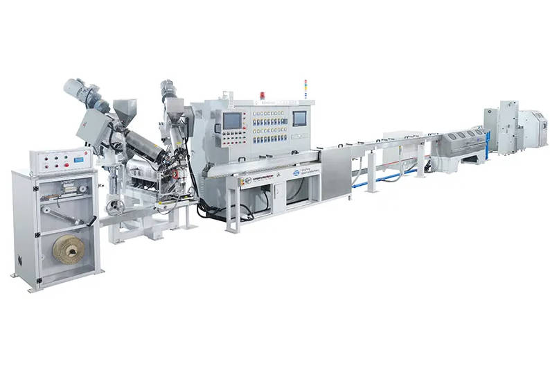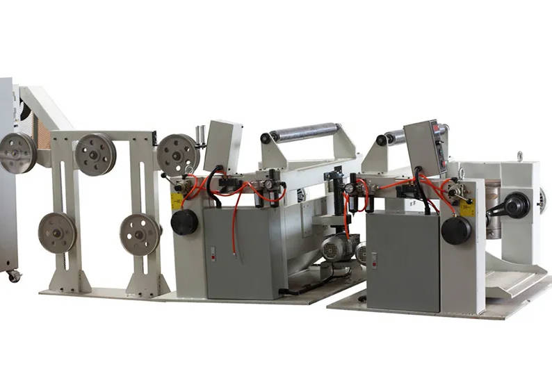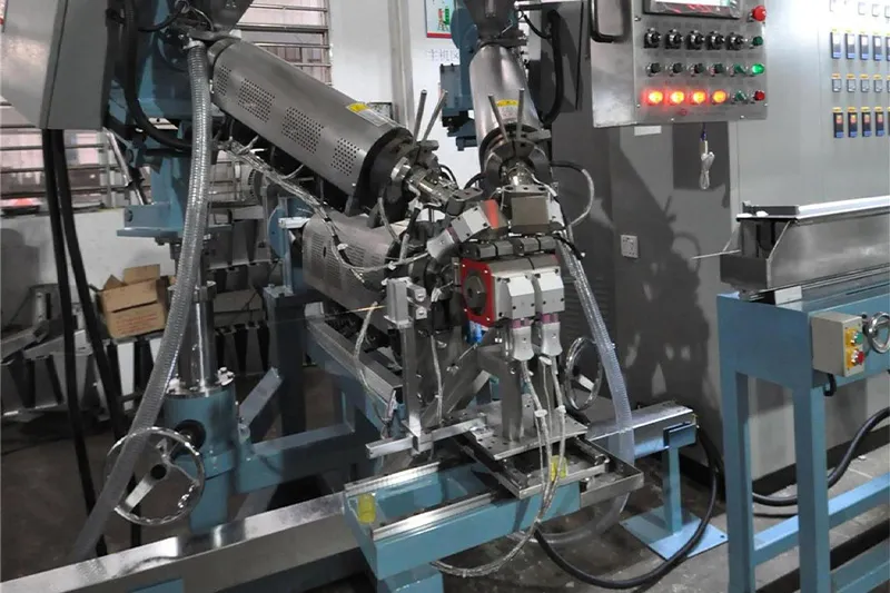
Selecting equipment for charging pile cable manufacturing requires matching machine dynamics directly to polymer shear sensitivity, strict concentricity tolerances, and continuous high-voltage insulation integrity. Because electric vehicle (EV) charging cables combine heavy-gauge power conductors with delicate signal cores under heavy, oil-resistant jackets, standard construction-wire extruders cannot deliver the required dimensional stability.
A dedicated extrusion line must balance gentle melt plasticization, multi-zone temperature stability, dynamic tension regulation, and closed-loop inline wall thickness verification. Evaluating these systems before issuing a purchase order prevents surface melt fractures, thermal degradation, core eccentricity, and excessive scrap rates during cross-linked or thermoplastic elastomer processing.
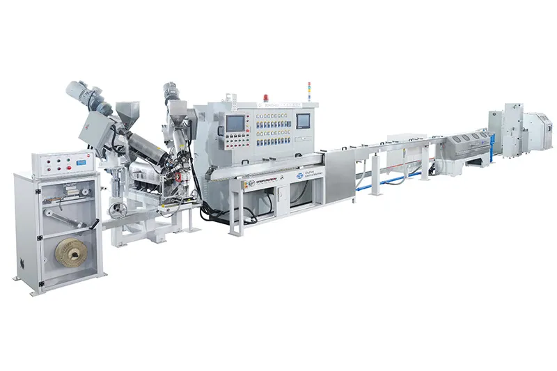
The Engineering Stakes of EV Charging Cable Manufacturing
EV charging cables (compliant with standards such as IEC 62893, EN 50620, or UL 2263) operate under severe mechanical and electrical stress. These assemblies undergo daily outdoor flexing, vehicle run-over pressure, UV exposure, and continuous high-current thermal loads.
To withstand these operating environments, cable designs utilize complex multi-conductor layouts bundled with control, pilot, and communication lines, enclosed by specialized elastomeric or cross-linked jackets. Converting these compounds into finished cables introduces distinct production risks:
Eccentricity and Dielectric Weakness: Uneven wall thickness leads directly to insulation breakdown under DC fast-charging voltage spikes.
Thermal Degradation: Shear-sensitive jacket polymers degrade if barrel friction spikes, causing micro-voids, bubbles, and compromised tensile strength.
Core Slippage and Loose Jacketing: Inconsistent crosshead pressure or improper vacuum application allows outer jackets to shift over inner cores during winding and field use.
Diameter Inconsistency: Fluctuations in take-up tension or screw melt output cause irregular outer diameters that fail connector overmolding checks.
Key Material Challenges: TPU, TPE, and Cross-Linked Compounds
Charging pile cables rely on specialized polymers tailored for harsh environments: Thermoplastic Polyurethane (TPU), Thermoplastic Elastomer (TPE/TPS), and cross-linked polyolefins (XLPO). Each material behaves differently inside the extrusion barrel.
| Material Type | Rheological & Extrusion Behavior | Primary Processing Risk | Machinery Requirement |
| TPU (Polyether / Polyester base) | Narrow processing temperature window; high melt viscosity; sensitive to shear heating. | Thermal degradation; discolored resin; melt fracture on surface. | Low-compression barrier screw; precision multi-zone barrel cooling (air/liquid). |
| TPE / TPV | High elastic recovery; shear-thinning; sensitive to draw-down ratios. | Wall thickness variation; uneven shrinkage; surface roughness. | Engineered crosshead flow channels; stable melt pressure control; dual-zone cooling. |
| XLPO / Halogen-Free Flame Retardant (HFFR) | High inorganic filler content (aluminum/magnesium hydroxide); abrasive melt; prone to premature scorch. | Screw wear; premature cross-linking/scorch in barrel; die drool. | High-torque drive; wear-resistant bi-metallic barrel; streamlined, zero-dead-zone crosshead. |
To maintain continuous compound integrity, modern facilities implement a configured cable extrusion line engineered specifically to process these engineering resins without exceeding thermal limits.
5 Critical Extrusion Line Subsystems Buyers Must Inspect
Evaluating machinery strictly by barrel diameter or raw motor horsepower overlooks the integration required for composite charging cables. Technical buyers should audit five specific sub-assemblies.
1. Screw Design and L/D Ratio for High-Viscosity Elastomers
Standard general-purpose screws create localized shear hotspots when handling TPU or highly filled halogen-free flame-retardant compounds.
L/D Ratio: Ratios between 25:1 and 28:1 are standard for shear-sensitive elastomers, providing sufficient homogenization without excessive residence time.
Flight Geometry: Look for barrier flights or specialized mixing heads (such as Maddock or pin mixers) optimized for low-temperature homogeneity.
Metallurgy: Bi-metallic barrels and hard-faced screw flights are necessary to prevent rapid abrasive wear from mineral flame retardants.
2. Temperature Control Precision and Barrel Cooling
Controlling heat generation is crucial because high melt viscosity generates significant internal friction.
Zone Division: The barrel should feature multiple independent heating/cooling zones (typically 4 to 6 on the barrel, plus adapter and crosshead zones).
Cooling Media: High-output blowers or closed-loop liquid cooling jackets must respond instantly to temperature rises above setpoints. Temperature controllers with fine PID tuning should maintain barrel temperatures within tight margins, typically targeting $\pm1^\circ\text{C}$.
3. Crosshead and Tooling Alignment for Concentricity
The crosshead determines roundness, wall uniformity, and adhesion to underlying braided shields or multi-core bundles.
Flow Channel Geometry: A streamlined flow distributor eliminates dead stagnation zones where TPU or cross-linkable compounds can degrade.
Centering Mechanism: Micro-adjustable or self-centering crossheads ensure concentric wall distribution. This prevents thin spots that cause high-voltage breakdown failures during certification tests.
Vacuum Integration: A regulated crosshead vacuum system draws molten elastomeric jackets into the outer interstices of the bundled cores when a tight-fill jacketing profile is specified.
4. Multi-Stage Cooling Troughs and Temperature Gradients
Quenching thick elastomeric outer jackets directly in cold water creates internal stress, surface wrinkles, and delayed shrinkage.
Graduated Cooling: Equipment setups should include multi-stage cooling. An initial warm-water section allows controlled solidification, followed by successive ambient and cold-water baths.
Trough Length: Trough length must accommodate the maximum anticipated line speed to ensure the cable core cools completely before reaching the haul-off unit.
5. Tension-Controlled Pay-Off and Take-Up Units
Heavy charging cables contain massive copper cross-sections (often up to $70\text{ mm}^2$ or more for DC fast charging) accompanied by fragile communication lines.
Constant Tension: Driven pay-off units with vertical or horizontal dancers must eliminate conductor elongation and core slack.
Caterpillar Haul-Off: Belt-type pullers should feature precise digital synchronization with the extruder drive to prevent slippage and continuous outer diameter drifting.
Take-Up System: Dual-reel continuous take-ups or portal-type winding units should provide smooth traversing to avoid pinching, jacket flattening, or bend-radius violations.
Quality Control Integration: In-Line Gauges You Cannot Skip
Manual caliper measurements during reel changes are insufficient for safety-critical automotive charging assemblies. High-specification lines require automated, closed-loop process monitoring:
| Production Sequence Stage | Inline Inspection Equipment | Control Mechanism & Action | Target Quality Parameter |
| 1. Primary Extrusion | Extruder & Crosshead | Initial polymer melt delivery and core covering | Base compound melt consistency |
| 2. Hot-End Dimensioning | Dual-Axis / Multi-Axis Laser Diameter Gauge | Real-Time Feedback Loop: Automatically adjusts Extruder RPM or Capstan Speed | Outer Diameter (OD) stability & draw-down control |
| 3. Wall Thickness & Concentricity | X-Ray or Ultrasonic Eccentricity Gauge | Instant Visual/Audio Alerts: Notifies operators to adjust crosshead centering alignment | Radial wall thickness uniformity & high-voltage safety margin |
| 4. Thermal Stabilization | Multi-Stage Cooling System | Graduated temperature reduction water baths | Controlled jacket shrinkage & internal stress relief |
| 5. Dielectric Integrity Check | High-Voltage Spark Tester | Defect Logging & Marking: Triggers audible alarm and logs fault coordinates for layer breakdown or pinholes | Continuous high-voltage insulation & jacket continuity |
| 6. Final Pull & Spooling | Synchronized Haul-Off & Take-Up | Tension-regulated puller and synchronized automatic traverse | Uniform coil layering & zero conductor stretching |
Non-Contact Diameter Gauges: Multi-axis laser scanning units continuously feed data back to the haul-off caterpillar and extruder motor drives to maintain tight dimensional envelopes.
X-Ray or Ultrasonic Eccentricity Measurement: These units provide instant cross-sectional analysis of multi-layer insulation and outer jackets, recording real-time wall thickness and concentricity percentages without cutting samples.
High-Frequency Spark Testers: Positioned after the final cooling and drying section, spark testers detect pinholes, micro-voids, and mechanical jacket breaches before the cable is coiled onto shipping spools.
How to Vet an Extrusion Line Manufacturer Beyond the Quotation
Procuring specialized machinery requires verifying an experienced extrusion line manufacturer based on technical validation rather than unit pricing alone. When vetting machine builders like Qingfeng, ensure your procurement team addresses several operational indicators:
Material Trial Runs (FAT): Confirm whether the manufacturer allows Factory Acceptance Testing using your specific formulation of TPU, TPE, or XLPO resin, rather than generic PVC pellets.
Component Provenance: Verify standard sourcing for critical elements, including PLC automation packages, variable frequency drives, temperature controllers, and main drive gearboxes.
Die and Tooling Engineering: Inquire whether crossheads and extrusion dies are engineered in-house to accommodate non-standard cable geometries, such as liquid-cooled or flat composite charging cables.
Commissioning and Field Support: Clarify on-site installation terms, mechanical calibration procedures, electrical commissioning, and replacement parts availability for high-wear components like screws and barrel liners.
Technical RFQ Checklist: What to Prepare Before Contacting Suppliers
To receive accurate technical proposals and line layouts, compile the following specifications before requesting quotations:
Cable Dimensional Profile: Minimum and maximum finished outer diameter (OD) and individual insulation core diameters.
Conductor Range: Conductor cross-sectional area (e.g., $2.5\text{ mm}^2$ up to $70\text{ mm}^2+$) and conductor structure (flexible Class 5 or Class 6 copper).
Compound Formulations: Exact jacket and insulation types (e.g., TPU, TPE, cross-linkable polyolefin, low-smoke zero-halogen).
Target Line Speeds: Required linear output rates (m/min) mapped to specific cable sizes.
Cooling & Utility Constraints: Available plant floor space, maximum cooling water circulation pressure, and total facility electrical capacity.
Key Takeaways
EV charging cable manufacturing requires specialized machinery designed for high-viscosity, shear-sensitive polymers like TPU and TPE; standard PVC extruders are not suitable.
Screws must feature barrier designs and moderate L/D ratios (typically 25:1 to 28:1) to prevent thermal degradation and melt fracture.
Tight tolerances demand multi-zone closed-loop cooling, self-centering crossheads, and graduated water troughs to control shrinkage and maintain concentricity.
Inline quality control—including continuous laser micrometers, eccentricity scanners, and spark testers—is essential to prevent costly insulation failures in high-voltage service.
Vetting machinery manufacturers requires confirming material trial runs (FAT), proven component sourcing, and tailored tooling capabilities before purchase.
FAQ
Can a single extrusion line handle both inner conductor insulation and outer cable jacketing?
While dual-purpose lines are mechanically possible by changing screws and crosshead tooling, industrial operations typically separate high-speed primary insulation extrusion from large-diameter jacket extrusion. Primary insulation requires higher line speeds and smaller screw outputs, whereas jacketing demands high-torque output, heavy pay-offs, and extended cooling troughs.
What is the primary risk of using standard screw geometry for TPU charging cable jackets?
Standard general-purpose screws generate uncontrolled frictional shear heat. This breaks down the molecular chains of the TPU, resulting in surface rough spots, discolored jackets, pinholes, and reduced tensile strength that fails flex-life testing.
Why is multi-stage graduated cooling necessary for EV charging cable jackets?
Thick elastomeric jackets quenched instantly in freezing water solidify on the outside while the inner core remains hot. This temperature difference locks in severe internal stress, causing ovality, uneven longitudinal shrinkage, and potential jacket separation over time.