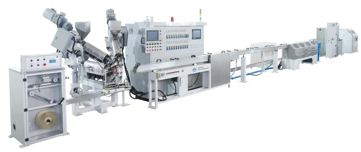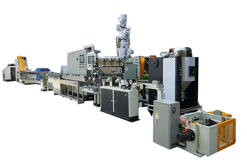
Maintaining tight insulation tolerances at line speeds exceeding several hundred meters per minute requires balancing mechanical alignment, polymer thermodynamics, and real-time process monitoring. In continuous wire manufacturing, cable extrusion line concentricity determines whether a finished conductor meets strict electrical insulation standards or fails spark testing due to localized thin spots. Achieving uniform wall distribution is not simply a matter of tightening head bolts; it requires steady melt pressure, dampening line vibrations, choosing the correct tooling geometry, and utilizing automated feedback loops.
This guide examines the mechanical and physical causes of eccentric insulation, outlines step-by-step crosshead alignment procedures, compares tooling options, and provides a structured troubleshooting framework to stabilize wall thickness during high-speed runs.
The Physics of Wall Variation: Why High-Speed Lines Amplify Eccentricity
Concentricity measures how centered a conductor sits inside its extruded insulation jacket. Mathematically, it represents the ratio between the minimum measured wall thickness and the maximum measured wall thickness across the same cross-section.
$$Concentricity (\%) = \frac{\text{Minimum Wall Thickness}}{\text{Maximum Wall Thickness}} \times 100$$
At lower line speeds, minor imbalances in melt flow or slight conductor wobble rarely push this ratio below acceptable thresholds. However, modern high-speed extrusion lines significantly amplify minor physical inconsistencies due to several coupled dynamics:
Non-Uniform Shear Heating: When screw RPM increases to supply high linear output, polymer friction against the barrel wall and screw flights generates intense localized shear heat. Even small temperature differentials across the melt channel lower polymer viscosity on one side of the crosshead. Lower-viscosity melt flows faster through the die, creating an uneven circumferential wall profile.
Melt Pressure Transients: High-speed throughput operates at elevated backpressures. Any slight fluctuation in screw feed rate, regrind composition, or barrel zone heating translates into cyclic pressure waves at the die land, showing up as lengthwise wall surging.
Conductor Dynamic Instability: Conductor wire passing through a crosshead at high linear velocity is subject to aerodynamic drag, mechanical resonance, and payout tension variations. A micro-vibration of a fraction of a millimeter inside the sizing die causes immediate wall thinning on the deflected side.
Crosshead Design and Tooling Setup for Optimal Concentricity
The mechanical interface between the bare conductor and the molten polymer—the crosshead assembly—is the primary mechanical determinant of wall symmetry.
Pressure Tooling vs. Tubing Tooling
Selecting the appropriate die tooling sets the baseline for concentric control:
| Parameter | Pressure Tooling | Tubing (Sleeve) Tooling |
| Material Application | Solid, non-jacketed primary wires, filling strand interstices | Thin-wall miniature conductors, high-speed data cables, loose-tube jackets |
| Melt Contact Point | Polymer contacts the conductor inside the die under high internal pressure | Polymer contacts the wire outside the die face via a draw-down cone |
| Centering Sensitivity | Extremely sensitive to core tube position and wire entrance angle | Tolerant of slight wire vibration; governed heavily by the Draw Down Ratio (DDR) |
| Wall Variation Risk | High head pressure can deflect thin or flexible conductors off-center | Draw resonance or uneven cone cooling can cause circumferential thin spots |
Crosshead Types: Self-Centering vs. Manual Centering
On standard lines, operators manually balance radial wall thickness using four radial adjustment bolts around the die body. While functional, manual adjustment presents significant challenges at high linear outputs: thermal expansion of the adjustment bolts can shift the die off-center as the machine reaches thermal equilibrium.
High-output facilities frequently utilize modern self-centering crossheads. These assemblies use fixed-position, high-precision manufactured guide cores and die holders configured to hold tight mechanical runout tolerances without operator bolt intervention. When paired with high-rigidity precision cable extrusion line configurations, self-centering heads eliminate operator setup error and maintain dimensional stability through startup, ramp-up, and continuous running phases.
Standard Crosshead Bolt Adjustment Protocol
| Step | Operation Stage | Action & Technical Requirement | Purpose / Precaution |
| 1 | Cold Pre-Torquing | Torque all radial adjustment bolts to a baseline specification at ambient temperature. | Establishes an even reference point and prevents cross-threading or uneven clamp loads. |
| 2 | Thermal Equilibrium | Allow the crosshead to reach target operating temperature and heat-soak for at least 30 minutes. | Prevents mechanical drift caused by uneven thermal expansion across tooling blocks. |
| 3 | Baseline Inspection | Check initial wall distribution via offline micrometer slicing or inline non-contact X-ray gauge. | Quantifies initial runout and isolates the exact angular vector of the thin wall. |
| 4 | Opposing Pair Tuning | Adjust bolts strictly in opposing pairs: always loosen the thin-wall side before tightening the thick-wall side. | Avoids binding the die holder or generating excessive localized mechanical stress. |
| 5 | Micro-Incremental Adjustment | Advance or retract adjustment bolts in micro-increments (1/16th to 1/8th of a turn per iteration). | Prevents tooling distortion, thread galling, and erratic over-correction swings. |
Thermal and Rheological Stabilization Across the Extruder Barrel
A perfectly aligned crosshead will still produce eccentric wire if the incoming polymer melt is thermally or rheologically inconsistent. Polymer flow follows the path of least resistance; lower-viscosity melt flows faster, directing excess volume to one side of the cable.
Mitigating Circumferential Temperature Gradients
To maintain a consistent melt stream:
Zone-Specific PID Tuning: The barrel zones closest to the feed throat must manage solids conveying, while transition and metering zones require tight cooling control to strip away excessive shear heat. Inadequate cooling in the metering section leads to hot spots that travel directly into the crosshead distributor.
Crosshead Heating Uniformity: Crossheads must be fitted with multi-zone heating bands to prevent the bottom or sides of the head from dropping below the target melt temperature. A delta of just 3°C to 5°C across the head body can induce enough viscosity shift to cause noticeable wall runout.
Melt Homogenization via Screw Design: For high-speed lines, dedicated barrier screws equipped with mixing sections (such as Maddock or pineapple mixers) are required to break up unmolten gels and level out radial temperature gradients before the polymer enters the adapter pipe.
Mechanical Dynamics: Line Tension, Guiding, and Vibration Control
Not all wall thickness issues originate in the extruder barrel or tooling. In high-speed operations, line mechanics upstream and downstream of the crosshead play an equally critical role in centering stability.
Conductor Payout ➔ Tension Dancer ➔ Preheater ➔ Wire Guide/Crosshead ➔ Water Troughs ➔ Haul-Off Capstan
[Zero Backlash] [Damped Drift] [Steady Temp] [Minimal Clearance] [Non-Turbulent] [Synchronized]
Payout Tension and Wire Guiding: If the pay-off tension fluctuates, the conductor oscillates as it passes into the core tube. Conductor guide tips must be sized precisely for the nominal bare wire diameter. Excessive guide-tip clearance allows the wire to wander within the melt stream; insufficient clearance can scratch conductor coatings or create tension spikes.
Cooling Trough Hydrodynamics: As coated wire leaves the die and enters the water cooling trough, turbulent water inlets or high-pressure spray headers can push the molten insulation off-center before it skins over. Water entry points should utilize non-turbulent, weir-style flow troughs or gradual cascade cooling to prevent hydraulic deflection of the soft polymer.
Tension Synchronization: The haul-off capstan and the main extruder drive must maintain precise digital synchronization. Minor slippage on the pulling capstan or speed hunting in the drive system shows up immediately as periodic, longitudinal wall thickness variation.
Closed-Loop Monitoring: Integrating Gauges and Automatic Feedback
Manual sampling using microscope cross-sections at reel changes is insufficient for high-speed production, as hundreds of meters of off-spec scrap can be generated before an operator detects a dimensional shift. Modern extrusion setups utilize non-contact, continuous measuring instrumentation integrated directly into the line’s PLC.
Sensor Technologies: X-Ray vs. Multi-Axis Laser
Multi-Axis Laser Gauges: Positioned immediately after the water trough (and often directly after the die for hot-diameter tracking), 2-axis or 4-axis laser scanners measure overall outer diameter (OD) and detect ovality. While fast and highly accurate for outer dimensions, lasers cannot measure the position of the internal conductor.
X-Ray Measurement Systems: X-ray sensors penetrate the insulation layer to detect the conductor core directly. This provides real-time wall thickness, outer diameter, and concentricity percentages across four or eight radial axes simultaneously, without physical contact.
Automated Feedback Control
When integrated with the line controller, measuring systems close the loop between measurement and mechanical correction:
Diameter Feedback (FFC): If the laser or X-ray unit detects a systematic drift in average OD or overall wall thickness, the controller automatically modulates the haul-off speed or extruder screw RPM to restore nominal thickness.
Thermal or Piezoelectric Crosshead Auto-Centering: Advanced systems route X-ray eccentricity data to automated crosshead modules. Using thermal expansion bolts or servo-driven adjustment pins, the system dynamically alters die orientation in micro-increments, compensating for process drift without manual operator intervention.
Troubleshooting Guide: Common Extrusion Defects and Remedial Actions
When wall thickness or concentricity deviates outside acceptable boundaries, use this structured checklist to isolate and correct the issue:
| Observed Symptom | Probable Root Cause | Recommended Corrective Action |
| Static One-Sided Thin Wall | Tooling misaligned; uneven crosshead heating band; mechanical core tip wear. | Check crosshead heater outputs; inspect guide tip for uneven wear; adjust die centering bolts opposingly. |
| Intermittent / Wandering Eccentricity | Conductor vibrating in guide tip; payout tension dancer hunting; turbulent water inlet. | Reduce guide tip inner diameter clearance; stabilize payout dancer backpressure; smooth cooling water entry flow. |
| Periodic Lengthwise Wall Surging (“Bambooing”) | Melt pressure instability; screw surging; haul-off capstan belt slippage or drive hunting. | Check barrel temperature profile for feed zone bridging; verify screw drive speed stability; inspect capstan belts for wear. |
| Ovality / Out-of-Round Insulation | Uneven drawdown in tubing die; premature one-sided cooling in trough; core wire twisted. | Adjust vacuum level inside the tubing crosshead; realign water trough guide rollers to submerge wire symmetrically. |
| Overall Wall Drifting Below Minimum Spec | Material melt index variation; screw speed drop; line speed acceleration drift. | Engage closed-loop haul-off/screw sync; verify resin batch MFI uniformity; adjust master line speed ratio. |
High-Speed Cable Extrusion: Frequently Asked Questions (FAQ)
What is the acceptable concentricity percentage for telecommunication and automotive wires?
Acceptable limits vary based on the applicable industrial standard (such as ISO 6722 for automotive or relevant UL/TIA standards for telecommunication). In general manufacturing practice, high-speed lines target a minimum concentricity of 90% to 95% to maintain signal integrity and ensure sufficient dielectric protection, while common building wires often operate with a lower threshold around 85%.
How often should crosshead assemblies be dismantled and cleaned?
Cleaning intervals depend heavily on the resin type. Thermally sensitive or filled materials (such as flame-retardant zero-halogen compounds or PVC) require more frequent teardowns to clear degraded char from flow splitters. Polyolefins (PE, PP) running on stable schedules may run extended shifts without disassembly, provided purge compounds are run during shutdown. Any build-up in the flow channels disrupts balanced polymer distribution and causes severe concentricity drift.
Can worn guide tooling cause sudden wall thickness drops?
Yes. If the guide tip’s internal bore wears oblong due to abrasive contact with high-speed wire conductors, the wire will wander radially within the crosshead. This causes dynamic eccentricity that cannot be corrected by adjusting the die centering bolts. Guide tips should be inspected regularly using optical comparators or plug gauges.
Upgrading Line Capabilities with Qingfeng Extrusion Technology
High line speeds test the mechanical limits of every component on an extrusion line. When processing conditions demand tighter concentricity tolerances, reduced startup scrap, and steady long-term wall thickness control, upgrading to rigid, high-precision equipment becomes essential.
Qingfeng designs and manufactures custom-engineered cable extrusion equipment tailored to stable, high-output wire manufacturing. From robust pay-off units and vibration-damped tension control systems to precision crosshead integrations and synchronized line drives, Qingfeng systems help manufacturers reduce material overconsumption while adhering to rigorous cable quality standards.
Key Takeaways
Speed Accentuates Mechanical and Thermal Flaws: High line speeds amplify minor melt temperature variations and conductor vibrations, turning minor flaws into out-of-spec concentricity defects.
Tooling Strategy Determines Baseline Stability: Tubing dies offer better dampening against conductor runout for thin-wall products, while pressure dies yield dense, void-free cores but require rigid wire guiding.
Thermal Balance is Crucial: Circumferential wall thickness depends heavily on uniform melt temperatures across the crosshead; minor temperature drops on one side shift flow distribution.
Upstream Dynamics Impact Crosshead Accuracy: Inconsistent payout tension, oversized guide tips, and turbulent cooling water introduce mechanical oscillations that make static die adjustments ineffective.
Inline Instrumentation Minimizes Material Loss: Real-time X-ray concentricity tracking and automated diameter feedback loops are critical for modern high-speed operations to eliminate undetected scrap.
FAQ
Q1: How does conductor preheating affect insulation concentricity?
A: Uneven conductor preheating causes the polymer to cool and shrink at different rates upon initial contact with the wire. Consistent preheat temperatures ensure uniform radial wetting, steady adhesion, and symmetric polymer cooling around the core.
Q2: Why does concentricity change as an extrusion line accelerates from startup to full speed?
A: Line acceleration increases shear heating in the barrel and changes the backpressure inside the crosshead. Conductor tension dynamics and cooling dynamics in the water trough also shift with velocity, making auto-feedback synchronization essential across the speed profile.
Q3: Can regrind material cause wall thickness variation?A: Yes. Inconsistent bulk density, irregular chip sizes, or melt flow rate variations between virgin resin and regrind can cause cyclic pressure fluctuations inside the barrel, leading to longitudinal wall thickness surging.