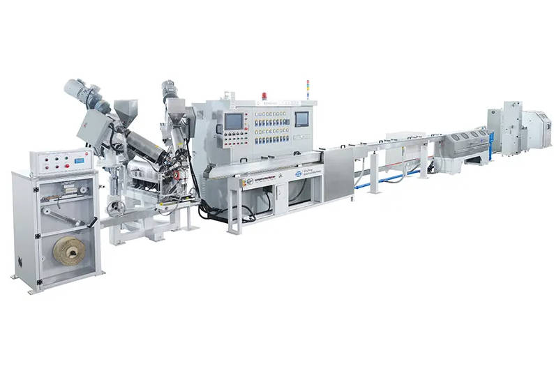
Electric power is one of the highest continuous operating expenses in wire and cable manufacturing. In a typical continuous extrusion plant, utility overhead is dominated by two primary subsystems: the mechanical drive powering screw rotation against melt resistance, and the thermal control units heating the extruder barrel and crosshead. Operating an energy-saving extrusion line requires replacing passive thermal dissipation and mechanical transmission drag with closed-loop motion control and directed heating technologies.
For cable manufacturers, overall plant operating expenditure correlates directly with specific energy consumption (measured in kilowatt-hours per kilogram of processed compound) and scrap rates generated during startup and line stabilization. This technical guide examines how synchronous drive systems, variable frequency controls, electromagnetic induction, and thermal insulation reduce baseline electricity demand, stabilize melt pressure, and shorten capital payback cycles.

The High Cost of Kilowatts: Mapping Energy Losses Across a Cable Extrusion Line
A continuous extrusion line converts electrical energy into kinetic energy to shear polymer chains and thermal energy to maintain processing viscosity. However, a significant portion of this supplied electricity never contributes to polymer plastification. Instead, it is lost through mechanical friction, motor cooling losses, and unshielded radiant heat transfer.
| Energy Input Stage | Loss Category | Primary Root Cause & Inefficiency Mechanisms | Typical Operational Impact |
| Total Line Electrical Input | Kinetic Losses (Motor & Powertrain) | • Rotor copper losses and low partial-load power factors in traditional induction motors • Internal mechanical friction, backlash, and oil churning in multi-stage gearboxes and transmission belts | Unproductive kilowatt draw, mechanical heat generation requiring secondary cooling, and elevated reactive power charges. |
| Total Line Electrical Input | Thermal Losses (Barrel, Collar & Crosshead) | • Continuous radial convective and radiant heat dissipation into the factory ambient air • Frequent, uncontrolled cooling water/blower cycles triggered to counteract thermal overshoot | Chronic thermal instability, unnecessary heating element cycling, and increased ambient workshop cooling load. |
In standard wire coating and jacketing lines, mechanical drive friction and barrel radiation account for the vast majority of preventable energy waste. When an uninsulated barrel operates at processing temperatures between 160°C and 240°C, ambient air constantly strips heat from the barrel exterior. Conventional band heaters must continuously cycle on to compensate for this thermal bleed. This continuous cycling not only consumes excess kilowatt-hours but also raises ambient workshop temperatures, placing an additional load on factory ventilation and cooling chillers.
Reducing line speed is rarely an effective cost-reduction strategy. Running an extruder below its optimal screw design point lowers output without proportionally decreasing motor core losses or barrel thermal radiation. Lowering production costs requires addressing the physical sources of mechanical resistance and thermal dissipation at the equipment design level.
| Extrusion Line Subsystem | Primary Energy Function | Dominant Energy Loss Mechanism | Engineering Mitigation Strategy |
| Main Extruder Drive | Converts electrical power to screw torque for resin conveying and shear | Rotor slippage, mechanical gearbox friction, low partial-load efficiency | High-efficiency PMSM direct-drive or closed-loop VFD motion packages |
| Barrel Zones | Supplies initial thermal energy for polymer melting and fluxing | Radiant and convective heat dissipation into ambient plant environment | Multi-layer ceramic insulation jackets or electromagnetic induction coils |
| Crosshead & Tooling | Maintains target melt viscosity and balanced flow at die entrance | Conductive heat loss across exposed clamping surfaces | Form-fitting thermal blankets and precise PID heating control |
| Capstan & Take-Up | Controls line tension, linear speed, and winding synchronization | Regenerative braking dissipation and asynchronous motor drift | Common DC-bus multi-drive architectures with regenerative power sharing |
Drive System Engineering: Moving from Conventional Motors to High-Efficiency Motion Control
The extruder drive package must deliver stable, high torque across wide speed profiles to process materials ranging from flexible PVC and low-smoke zero-halogen (LSZH) compounds to high-density polyethylene (HDPE). Conventional extrusion lines typically pair standard AC induction motors with multi-stage reduction gearboxes. While mechanically robust, this configuration introduces inherent electrical and mechanical inefficiencies.
| Drive Topology | Mechanical Transmission Chain | Efficiency Profile | Maintenance Overhead |
| Conventional Geared Drive | Standard AC Motor $\rightarrow$ Flexible Coupling $\rightarrow$ Multi-Stage Reduction Gearbox $\rightarrow$ Screw Thrust Block | Mechanical friction, shear losses in lubrication oil, and gear backlash lead to transmission loss | High: Regular oil changes, seal replacements, bearing checks, and gear wear monitoring |
| Advanced Direct Drive | Permanent Magnet Synchronous Motor (PMSM) $\rightarrow$ Directly Coupled Screw Shank | Eliminates transmission wear; delivers full torque smoothly across low-to-high RPM bands | Low: Zero lubrication oil required, no gear backlash, and minimal moving wear parts |
Permanent Magnet Synchronous Motors (PMSM) and Direct-Drive Advantages
Modern energy-efficient extrusion line engineering increasingly incorporates Permanent Magnet Synchronous Motors (PMSM) or torque motors coupled directly to the thrust bearing housing.
Elimination of Gearbox Losses: Traditional reduction gearboxes experience mechanical friction across gears, bearings, and oil churning. Depending on the gear stages and operating conditions, this transmission loss can consume significant shaft power. Direct-drive configurations couple the motor directly to the screw shank, eliminating these mechanical gear interfaces.
High Torque at Low Operating Speeds: Standard induction motors lose torque and thermal self-cooling capacity at low operating frequencies, often requiring oversized frames to handle the high starting torque of filled cable compounds. PMSM units maintain continuous rated torque from near-zero speeds up to full rated velocity, preventing motor stalling during cold restarts or line ramp-up.
Optimized Power Factor: Induction motors exhibit poor power factor under partial loading, drawing excessive reactive current that strains plant transformers and risks utility power factor penalties. Synchronous permanent magnet motors maintain a power factor close to unity across broad operating envelopes.
Variable Frequency Drives (VFD) Under Fluctuating Extrusion Loads
Pairing advanced motors with modern Variable Frequency Drives (VFDs) ensures that electrical draw corresponds strictly to the mechanical shear resistance inside the barrel.
Dynamic Inverter Switching: Advanced inverters modulate voltage and frequency through field-oriented vector control (FOC). By monitoring instantaneous rotor position, the drive calculates the exact torque current required to overcome resin viscosity variations without excessive current spikes.
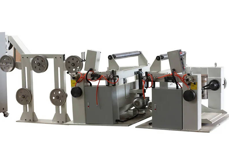
Line Coordination and Common DC-Bus Architectures: In integrated extrusion lines where the extruder, haul-off capstan, and dual-reel take-up run synchronously, decelerating drives can feed regenerative energy back into a shared DC bus. The main extruder drive or auxiliary heating zones can immediately consume this reclaimed kinetic energy rather than burning it off across braking resistors as waste heat.
Thermal Optimization: Upgrading Barrel and Collar Heating for Maximum Heat Transfer
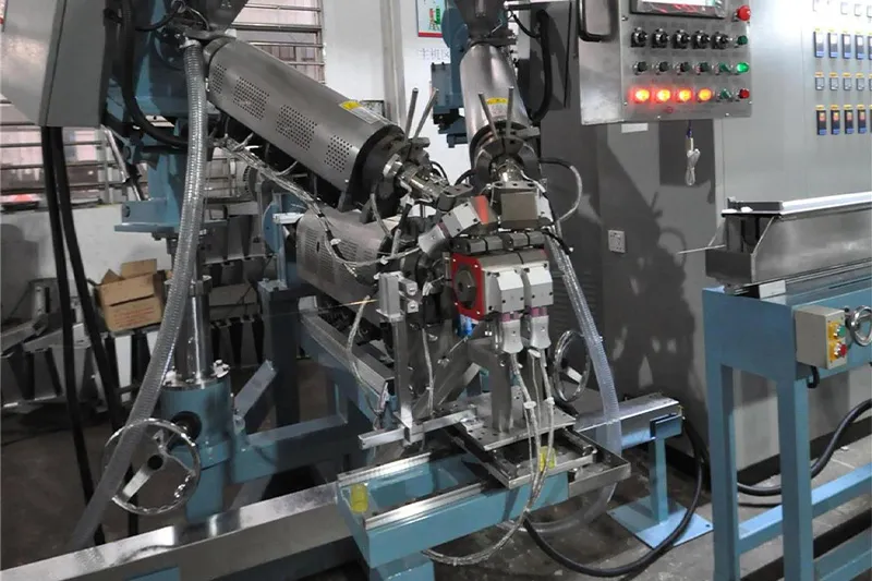
Thermal management requires striking a balance between input heat, mechanical shear heat, and ambient dissipation. Standard cast-aluminum band heaters transfer heat primarily through external thermal conduction. Because the heating element resides inside a metal casting that radiates outward as freely as it does inward, a substantial portion of the generated heat is lost to the factory floor.
| Heating Mechanism | Operating Principle | Heat Transfer Direction | Energy Retention Characteristics |
| Cast-Aluminum Band | Resistance wire inside cast aluminum casing | Radial inward conduction to barrel wall, simultaneous outward radiation to room air | Significant heat lost to ambient air unless fitted with secondary insulation |
| Electromagnetic Induction | High-frequency alternating magnetic flux penetrates insulation to excite barrel steel directly | Direct volumetric eddy current heating inside the barrel wall | Thermal barrier prevents outward heat loss, keeping surface casing cool |
Cast Aluminum vs. Ceramic Band vs. Electromagnetic Induction Heating
Selecting the optimal barrel heating technology depends on target processing temperatures, resin thermal sensitivity, and production shifts.
Cast Aluminum Bands: Functional for lower-temperature operations (e.g., standard PVC insulation), but structurally limited in thermal transfer efficiency. Without external insulation blankets, outer shell temperatures often approach internal melt settings, representing continuous energy waste.
Insulated Ceramic Band Heaters: Incorporate high-grade ceramic fiber blankets beneath an outer stainless-steel sheet. These units reduce external shell skin temperatures, directing a higher fraction of electrical energy radially inward toward the barrel liner.
Electromagnetic Induction Heating: Rather than transferring heat from an external resistance element inward through the barrel wall, an induction coil generates a high-frequency alternating magnetic field. This field passes through non-conductive thermal insulation and induces eddy currents directly within the steel barrel itself. The barrel wall becomes its own heating element, allowing fast heat generation with minimal energy lost to the surrounding environment.
| Heating Technology | Primary Heat Transfer Mode | External Surface Temperature | Pre-Heating Cycle Speed | Relative Energy Conservation Potential |
| Cast Aluminum Bands | Thermal conduction from resistance wire via cast aluminum | High (Often exceeds 120°C–180°C) | Standard baseline | Baseline |
| Insulated Ceramic Bands | Conduction with integrated back-insulation layer | Moderate (Typically 60°C–90°C) | 15% to 25% faster than cast aluminum | Moderate reduction in radial heat loss |
| Electromagnetic Induction | Direct electromagnetic excitation of the steel barrel | Low (Typically safe to touch, < 50°C–60°C) | 30% to 50% faster than conventional bands | Significant reduction in thermal dissipation |
Barrel Insulation Jackets and Melt Temperature Stability
For installations retaining resistance band heaters, custom-engineered, multi-layer thermal insulation jackets provide an immediate defense against heat bleed. Fabricated from silica or ceramic-fiber insulation encased in silicone-coated fiberglass textiles, these removable blankets insulate the barrel zones, flange adapters, and crosshead tooling.
Maintaining a thermally insulated barrel stabilizes internal temperature profiles against drafts and ambient shop variations. When the outer thermal boundary remains constant, PID temperature controllers experience fewer overshoots and undershoots. This stability prevents the cooling blowers from triggering unnecessarily—a common fault in uninsulated extruders where heating elements and cooling blowers fight each other, wasting both electricity and compressed air.
The Synergy: How Stable Drives and Closed-Loop Heating Prevent Resin Waste
Energy efficiency in cable manufacturing extends beyond the electrical meter. Scrap reduction is an equally critical component of plant sustainability. Extruding out-of-spec wire wastes both polymer resin and the cumulative electricity previously spent melting, forming, cooling, and winding that scrapped product.
| Process Stage | Physical Cause of Process Instability | Direct Production Consequence | Cumulative Economic & Energy Cost |
| Screw Drive Motion | Motor speed hunting, line frequency drift, or mechanical backlash in gears | Dynamic melt pressure surges at the breaker plate and crosshead | Non-uniform wall thickness along the wire axis |
| Barrel Temperature Control | Thermal boundary fluctuations and uninsulated zone overshoot | Resin melt viscosity changes across barrel zones | Core conductor eccentricity and uneven crosshead flow |
| Finished Extrusion Run | Inability to maintain target outer diameter (OD) within tight tolerances | Off-spec finished cable requiring manual scrap stripping | Wasted raw compound plus unrecoverable kilowatt-hours spent processing |
Screw RPM Consistency Prevents Surging: In conventional induction motor drives, utility line voltage sags or mechanical gear backlash can induce slight rotational speed variations. These fluctuations create pressure surges at the breaker plate, causing wall thickness variations along the length of the cable. Synchronous drives provide steady shaft rotation, maintaining uniform volumetric displacement.
Accurate Thermal Profiles Protect Melt Homogeneity: If barrel temperatures fluctuate across zones due to uninsulated heating elements, the polymer’s viscosity changes dynamically. Variations in melt viscosity alter the center point of the conductor within the crosshead, causing wall thickness and concentricity drift. Operators often compensate by deliberately increasing minimum wall thickness to avoid compliance failures—unintentionally consuming excess compound per kilometer of finished cable.
Closed-Loop Synchronization Reduces Startup Purging: Modern production lines equipped with coordinated motion control and rapid-heating induction systems reach stable operating equilibrium faster following a cold start or compound changeover. Reducing the time required to achieve target melt temperatures and crosshead pressures directly cuts the volume of purging scrap generated before production begins.
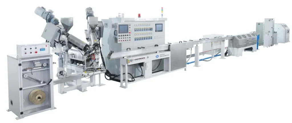
Manufacturers evaluating complete Qingfeng extrusion lines benefit from this holistic integration, where motion control and thermal regulation communicate over high-speed industrial fieldbus architectures to maintain process repeatability and minimize resin waste.
B2B Buyer’s Decision Matrix: Evaluating Payback Periods for Energy-Efficient Lines
Investing in premium drive systems and high-efficiency thermal architectures requires technical and financial justification. Plant engineers and procurement managers must evaluate overall lifecycle operating costs rather than focusing solely on initial capital machinery cost.
| Operating Evaluation Metric | Conventional Extrusion Line | Modern Energy-Saving Extrusion Line | Financial & Operational Return Factor |
| Initial Capital Outlay (Capex) | Lower initial purchase price | Higher initial investment for PMSM motors, VFDs, and induction systems | Premium compensated by reduced utility and maintenance costs |
| Specific Energy Consumption | Higher baseline kWh per kilogram of processed compound | Measurably lower kWh per kilogram of processed compound | Continuous reduction in monthly utility overhead |
| Startup / Purge Material Scrap | Longer pre-heating and slower pressure stabilization generate more purge waste | Fast thermal response and closed-loop pressure control reduce startup scrap | Direct savings on resin consumption and rework overhead |
| Routine Powertrain Upkeep | Periodic gear oil changes, seal replacements, and mechanical alignment checks | Direct drive eliminates reduction gears and associated lubrication tasks | Lower labor costs and minimized unplanned line downtime |
Key Variables in Extrusion Energy Audits (kWh per Kilogram Produced)
To establish an accurate operational baseline, calculate the Specific Energy Consumption (SEC) of existing equipment:
$$\text{Specific Energy Consumption (SEC)} = \frac{\text{Total Line Active Power Consumption (kWh)}}{\text{Net Output of Qualified Cable Insulation/Jacket (kg)}}$$
When conducting an on-site energy audit, engineering teams should evaluate:
Baseline Running Draw: Active power (kW) measured across steady-state running conditions, segmented by the motor drive cabinet and barrel heating zones.
Thermal Loss Differential: Surface temperature readings taken across the barrel, adapter zones, and crosshead using calibrated thermal imaging cameras.
Annual Operating Hours: Facilities operating continuous multi-shift schedules (e.g., 6,000 to 8,000 hours per year) reach capital payback significantly faster than batch-style, single-shift plants.
Local Utility Tariffs: Baseline kWh pricing, tiered peak-demand penalties, and regional energy efficiency incentives or equipment upgrade rebates.
Assessing Retrofitting Existing Units vs. Procuring a New Extrusion Line
Plant managers must decide between retrofitting existing machinery and investing in a newly engineered line.
| Evaluation Stage | Primary Diagnostic Question | Retrofit Path Recommendation | Complete New Line Procurement Path |
| Mechanical Integrity | Are the current barrel, screw, and thrust bearing housings in good condition? | If mechanical components are sound, consider upgrading heater bands or insulation jackets. | If the mechanical base shows severe wear, procuring a new production line prevents compounding downtime. |
| Powertrain Space & Controls | Does the chassis support a direct-drive PMSM motor and modern digital bus? | Space constraints may limit upgrades to drop-in VFD packages and standard motors. | Full integration allows matched inertia, optimized screw geometry, and unified PLC automation. |
| Economic Payback Profile | What is the total cost of ownership over a 5-to-10-year production window? | Lower upfront expense, but legacy transmission losses and controls bottlenecks remain. | Higher initial capital expenditure offset by maximum energy savings, lower scrap, and OEM warranties. |
The Retrofit Path: Upgrading an older machine with ceramic insulation blankets or modern vector inverters can be a cost-effective, low-capital project. However, retrofits often run into space constraints around older thrust bearing mounts, legacy PLC communication bottlenecks, and the structural limitations of aging gearboxes.
The Complete Line Procurement Path: Procuring a purpose-built custom cable extrusion line guarantees matched powertrain inertia, screw geometry optimized for specific resin shear characteristics, and unified PLC automation. The resulting improvements in line speed, concentricity control, and energy efficiency typically provide a predictable return on capital.
Key Takeaways
Target the Primary Energy Consumers: Drive train operation and barrel thermal management account for the majority of electrical power consumed across an extrusion plant.
Eliminate Mechanical Transmission Drag: Direct-drive permanent magnet synchronous motors remove gearbox friction, lower maintenance requirements, and maintain high torque efficiency across wide speed ranges.
Shield Thermal Losses: Electromagnetic induction and insulated ceramic heating elements reduce radiant heat loss to the plant floor, shorten startup heating times, and stabilize melt temperature profiles.
Recognize Scrap Reduction as an Energy Saving: Stable motor speeds and consistent barrel thermal control eliminate melt pressure fluctuations, preventing cable dimensional variations and reducing scrap resin volume.
Evaluate Investments on an SEC Basis: Base equipment selection on Specific Energy Consumption ($kWh/kg$) and total operating lifecycle hours rather than initial machinery purchase price alone.
Frequently Asked Questions (FAQ)
How much power does a typical cable extrusion line consume per hour?
Total electrical consumption depends heavily on the screw diameter, cable core cross-section, target output capacity ($kg/h$), and the specific resin processed (e.g., PVC, PE, XLPE, or fluoropolymers). A compact core wire insulation line may draw less than 30 kW, whereas a high-output, continuous jacketing line processing tough engineering polymers can draw well over 150 kW. The primary engineering metric used to compare machines across manufacturers is Specific Energy Consumption ($kWh/kg$), which evaluates energy consumed per unit of processed compound.
Can older cable extrusion lines be retrofitted with electromagnetic heating?
In many cases, yes. Resistance bands can be replaced with induction coils and matching high-frequency power controllers, provided there is adequate physical clearance along the barrel zones and around cooling blowers. However, plant engineers must verify that the machine’s existing PLC or temperature control modules can manage the faster thermal response times of induction coils without experiencing temperature overshoot.
How do servo or PMSM drives improve cable insulation concentricity?
Concentricity issues often stem from subtle melt pressure fluctuations at the crosshead die. Traditional induction motors can exhibit minute rotational speed variations under fluctuating line loads or utility voltage changes. PMSM drives operate synchronously with inverter frequency, delivering uniform rotational velocity regardless of load variations. This steady delivery maintains constant melt pressure, resulting in uniform wall thickness and concentricity around the conductor.
What is the primary maintenance difference between direct-drive and geared extruders?
Direct-drive extruders eliminate the reduction gearbox entirely. This design removes the need for periodic gearbox lubricant changes, seal replacements, and mechanical alignment checks. It also eliminates failure modes associated with gear wear, backlash, and mechanical bearing degradation, reducing downtime and maintenance overhead over multi-year production campaigns.