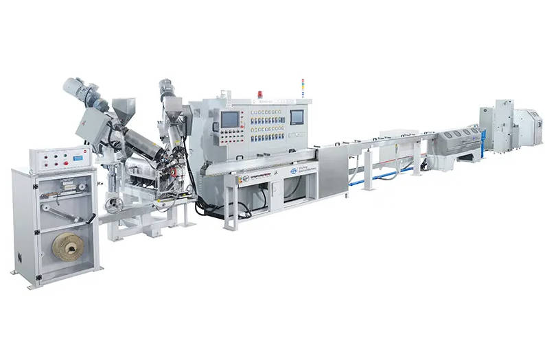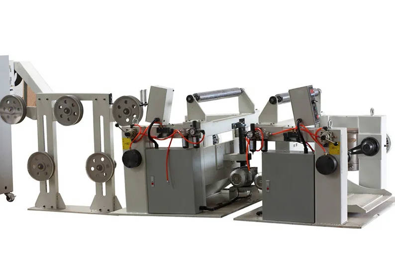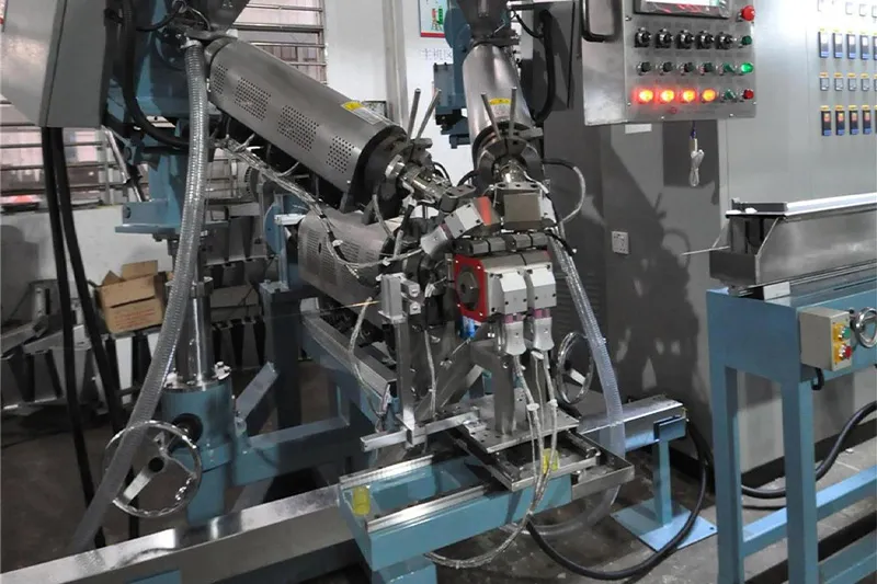
Direct inline testing is the only reliable way to detect insulation pinholes, voids, and thin spots before a cable reaches the take-up reel. Implementing effective spark testing in cable extrusion line operations requires resolving two core engineering questions: exactly where to locate the test electrode along the line, and how to calibrate the test voltage and sensitivity to line speed and wall thickness.
Locating the tester too close to the cooling trough causes residual water droplets to trigger false breakdown alarms. Conversely, placing it too far downstream or running improper sensitivity levels risks passing unaddressed dielectric faults directly onto shipping spools. This engineering guide examines optimal physical positioning, voltage calibration rules, electrode technology choices, and PLC synchronization methods required to maintain continuous insulation integrity.
The Role of Inline Spark Testing in Insulation Defect Detection
An inline spark tester subjects moving insulated wire or cable to a continuous high-voltage electrical field without stopping production. The core conductor is maintained at earth ground through the line machinery (typically via the pay-off, capstan, or dedicated grounding pulleys), while the outer surface of the insulation passes through an energized electrode containing metallic bead chains or conductive brushes.
When the insulation is intact, it acts as a dielectric barrier, preventing current from passing from the electrode to the grounded core. If a pinhole, hairline slit, bare patch, or void passes through the test field, the air gap inside the fault breaks down, creating a momentary electrical discharge (a spark). The tester registers this micro-fault as a current spike and signals the plant control system.
Unlike destructive post-production tank immersion testing—which evaluates finished coils off-line—inline spark testing enables real-time fault identification at production speeds. When paired with automated marking and line alarms, it prevents extensive scrap production and guarantees that finished reels comply with international dielectric standards such as UL 1581 and IEC 62230.
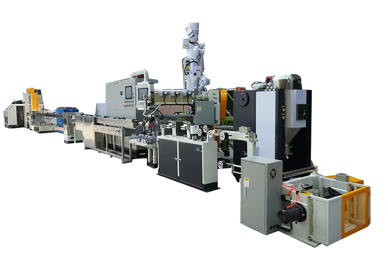
Physical Placement Strategy Along the Extrusion Line
The physical position of the spark tester relative to upstream cooling and downstream haul-off equipment dictates whether fault detection is clean and dependable or plagued by intermittent false alarms.
1. Extrusion Line Sequence Layout
On an industrial wire and cable manufacturing line, equipment must follow a strict sequential order to isolate the spark tester from residual moisture and line tension variances:
| Process Sequence | Production Stage / Equipment | Functional Role in Quality Control |
| Stage 1 | Extrusion Crosshead | Melts and coats polymer compound onto conductor. |
| Stage 2 | Water Cooling Trough | Solidifies insulation layer in multi-stage temperature zones. |
| Stage 3 | High-Velocity Air Wiper | Strips residual surface moisture and boundary water layers. |
| Stage 4 | Laser Diameter Gauge | Verifies outer diameter, ovality, and wall thickness uniformity. |
| Stage 5 | Spark Tester | Continuous high-voltage inline dielectric defect detection. |
| Stage 6 | Caterpillar / Capstan Haul-off | Provides stable pulling tension and continuous line speed control. |
| Stage 7 | Defect Marking System | Applies localized ink/spray mark synchronized with encoder data. |
| Stage 8 | Dual Take-up & Accumulator | Continuous take-up spooling and automatic scrap spool isolation. |
2. Moisture Control and Air Wiper Clearance
The cable must be completely dry before entering the spark tester electrode. Residual water film, localized droplets, or moisture tracking along conductor surface grooves conduct electricity over the cable jacket, creating premature flashovers to the electrode chassis. This generates false fault counts and can degrade the jacket surface.
Install high-velocity air wipes or multi-stage blowers immediately after the water trough exit.
Maintain a clearance gap of at least 1.0 to 1.5 meters between the air wipe exit and the spark tester inlet. This distance allows residual surface humidity to evaporate before the cable enters the high-voltage field.
3. Haul-off and Vibration Management
Cable vibration inside the bead-chain box causes intermittent contact, leading to erratic spark discharges and mechanical wear on thin-wall insulation. Positioning the spark tester just ahead of a stable capstan or caterpillar puller stabilizes line tension. Guiding rollers or ceramic eyelets must be installed at both the entrance and exit of the tester housing to keep the conductor strictly centered along the electrode centerline.
| Placement Zone | Evaluation | Operational Consequence |
| Immediately after cooling trough (Without Air Wipe) | Unsuitable | Water carryover causes continuous false trips and surface tracking. |
| After multi-stage air wipe, before capstan | Optimal | Stable cable path, dry jacket surface, and immediate detection before pulling tension increases. |
| After capstan, immediately before take-up | Acceptable with constraints | Eliminates tension-induced sag, but increases the length of scrap cable between fault point and downstream stop point. |
Spark Tester Technology Selection: HF vs. AC vs. DC
Selecting the correct spark tester architecture depends directly on line running speed, cable diameter, and capacitive loading characteristics.
| Operating Criteria | Line Speed & Product Condition | Recommended Technology | Electrical Characteristics |
| High-Speed Extrusion | Line Speed > 150 m/min Thin to Medium Wall Insulation | High-Frequency (HF) Sinusoidal / Pulsed | • Operating frequency: 2.5 kHz – 4.0 kHz • Compact electrode chamber (50–120 mm) • Low capacitive charging load |
| Low-Speed / Heavy Extrusion | Line Speed < 100 m/min Heavy Industrial / Thick Walls | Mains Frequency (AC) or Continuous DC | • Operating frequency: 50 Hz / 60 Hz (AC) or Pure DC • Extended electrode chamber (500–1500 mm) • High capacitive load (AC) / Zero capacitive drop (DC) |
High-Frequency (HF) Spark Testers (Typical: 2.5 kHz to 4.0 kHz)
High-frequency sinusoidal testers are the standard for modern high-speed extrusion lines (ranging from 200 m/min to over 1,500 m/min). Because of the high frequency, the electrode length can be significantly shorter—often only 50 mm to 120 mm—while still guaranteeing sufficient electrical contact cycles as the cable moves through the bead chain. The reduced electrode size minimizes line footprint, eliminates line sag inside the tester, and significantly reduces capacitive charging currents, preventing burn marks on delicate wire products.
Mains Frequency AC Testers (50 Hz / 60 Hz)
Mains AC testers rely on long bead-chain chambers (often 500 mm to 1,500 mm) to ensure that every point along the running wire experiences multiple complete sinusoidal cycles at moderate speeds. They are generally restricted to slow extrusion processes (under 100 m/min), such as heavy building wires, power core insulation lines, or thick jacketing applications. Because of their large physical footprint and high capacitive loading, they are less suitable for high-speed automated extrusion lines.
Direct Current (DC) Spark Testers
DC spark units continuously charge the insulation surface without capacitive current switching losses. They are primarily selected for large-diameter power cables, thick insulation walls, or coaxial line monitoring where high AC capacitance would overload a standard test transformer. However, DC testing leaves residual surface electrostatic charges that require post-test grounding discharge brushes to prevent shock hazards to downstream operators.
| Technical Parameter | High Frequency (HF / 3 kHz) | Mains Frequency AC (50/60 Hz) | Direct Current (DC) |
| Optimal Line Speed | High to Ultra-High (> 150–1500 m/min) | Low (< 80–120 m/min) | Low to Medium (< 150 m/min) |
| Electrode Chamber Length | Short (approx. 50–120 mm) | Long (approx. 500–1500 mm) | Medium (approx. 200–500 mm) |
| Capacitive Loading on Line | Low | High | None (after initial charge) |
| Typical Target Products | Automotive wire, LAN cables, THHN | Heavy power cores, thick jackets | High-voltage insulation, rubber cables |
Calibrating Sensitivity and Test Voltage
Operating an inline spark tester effectively requires balancing two parameters: the voltage must be high enough to break down structural flaws, yet low enough to prevent dielectric puncture of sound material.
1. Test Voltage Selection
The required test voltage ($V_{test}$) is primarily governed by the nominal radial wall thickness ($t_n$) and the dielectric strength of the insulating compound (e.g., PVC, HDPE, XLPE, FEP).
Industry standards provide strict tables correlating wall thickness and conductor gauge to test potential:
For thin-wall primary insulation ($0.15 \text{ mm} – 0.40 \text{ mm}$), test voltages generally range from $1.5 \text{ kV}$ to $4.0 \text{ kV}$ HF.
For standard industrial building wire ($0.6 \text{ mm} – 1.2 \text{ mm}$), test voltages often range from $5.0 \text{ kV}$ to $10.0 \text{ kV}$ AC/HF.
The test voltage must remain well below the ultimate breakdown strength of the sound polymer, typically applying a safety factor of 2.5 to 3.0 times the intended operational service rating.
2. Dwell Time and Line Speed Synchronization
The cable must remain within the high-voltage electrical field long enough to experience a sufficient number of electrical cycles. Under IEC 62230 and UL standards, moving wire should generally experience a minimum exposure duration (dwell time) inside the active electrode, often recommended at $0.015 \text{ seconds}$ or at least 9 to 18 voltage wave cycles.
The relationship between electrode length, line speed, and dwell time is defined by:
$$\text{Dwell Time } (s) = \frac{\text{Electrode Length } (\text{meters})}{\text{Line Speed } (\text{meters/second})}$$
If an extrusion line accelerates from $300 \text{ m/min}$ ($5 \text{ m/s}$) to $900 \text{ m/min}$ ($15 \text{ m/s}$), an electrode that provided adequate dwell time at low speed may under-test the cable at high speed unless paired with a higher-frequency field or extended electrode box.
3. Fault Sensitivity Adjustment
Sensitivity settings dictate the current detection threshold and the response time required to log a fault:
Under-sensitive: The tester fails to register high-resistance arc paths through micro-pinholes before the fault passes outside the chamber.
Over-sensitive: Atmospheric humidity changes, minor corona discharges, or static field variations register as phantom insulation breaches, triggering unnecessary line stoppages.
The detection circuit should identify pinhole discharges lasting down to 20 to 50 microseconds without triggering on nominal capacitive charging currents.
Control System Integration: Feedback, Marking, and Take-Up Synchronization
An inline spark tester must function as an integrated component of the overall line control system rather than a disconnected inspection device. Integrating the unit with a modern cable extrusion line requires low-latency communications and reliable defect tracking across downstream equipment.
| Integration Channel | Signal Type & Protocol | Triggered Production Action |
| Real-Time Discrete Channel | Hardwired 24V Relay / High-Speed Optocoupler | • Triggers downstream inkjet or paint spray marker. • Activates visual and audible line alarm stack. • Shifts take-up drive to controlled crawl speed. |
| Digital Fieldbus Channel | Industrial Ethernet / Profinet / Modbus TCP | • Logs exact fault location meter count into batch recipe. • Records real-time voltage and current drop waveforms. • Automates dual-spool cut-and-transfer sequence. |
1. Defect Tracking and Downstream Marking
When an insulation breakdown occurs, the tester’s output relay triggers high-speed PLC input cards. Because the tester sits several meters upstream of the take-up unit, the PLC must incorporate an encoder-based position shift register:
The line encoder measures precise linear wire travel from the spark electrode to the downstream marking device.
An industrial inkjet printer or spray marker applies a bright, contrasting color patch directly over the defect zone.
Operators can quickly identify, cut out, or splice past the defective section during final rewinding or multi-core cabling.
2. Take-Up and Line Speed Actions
Depending on the cable category and factory quality protocols, the PLC executes one of three automated responses upon defect confirmation:
Continuous Run with Marker: Used for mass commodity conductors where faults are marked and excised during post-extrusion rewinding.
Controlled Deceleration: The extrusion line decelerates to crawl speed, allowing the operator to inspect the jacket for tooling damage, melt fracture, or centering eccentricity.
Dual Take-up Automatic Transfer: On fully automated extrusion setups, fault triggers can command the take-up to transfer the wire to an alternate reel, isolating defective lengths onto a scrap spool.
Troubleshooting Inline Spark Testing Faults
When testing issues arise, the cause is often line setup conditions rather than instrument malfunction. Use this checklist to isolate common problems:
| Problem Observed | Probable Root Cause | Engineering Solution |
| Repetitive False Defect Alarms | Surface moisture carried from cooling trough. | Adjust air wipe positioning; replace worn air wiper nozzles; increase drying pressure. |
| Electrode bead chains soiled with carbon or polymer dust. | Clean bead chains using industrial alcohol; replace broken or missing chain links. | |
| Test voltage set above dielectric strength of polymer. | Verify jacket thickness with online diameter gauge; recalibrate voltage to production specifications. | |
| Undetected Insulation Voids (Reported Downstream) | Core conductor grounding connection is poor or broken. | Check continuity from pay-off spindle and capstan wheels to factory ground rods. |
| Line speed exceeds electrode dwell time capability. | Switch to higher-frequency tester (e.g., 3 kHz HF) or increase effective electrode length. | |
| Spark sensitivity threshold dialed too low. | Recalibrate instrument sensitivity using standard artificial fault spark simulator. | |
| Arcing Marks / Jacket Scratches | Cable entering electrode off-axis, rubbing enclosure walls. | Realign input/output ceramic guide wheels with line centerline. |
| Excessive voltage applied to thin-wall insulation. | Lower test voltage to standard threshold; check wall concentricity. |
Engineering Considerations When Sourcing an Integrated Extrusion Line
High-performance testing depends heavily on mechanical stability. Cable vibration, tension instability, and poor grounding across the line can disrupt dielectric monitoring even with a properly calibrated tester.
When collaborating with a cable extrusion line manufacturer, verify the following integration features:
Vibration Damping Mounts: Structural mounting brackets must isolate the spark tester from mechanical vibrations generated by nearby high-speed haul-offs or extruders.
Integrated Drying Enclosures: Closed-loop air wiping systems should drain water directly back into the cooling trough to keep the testing area dry.
Grounding Brush Design: Grounding contacts must maintain continuous physical contact with bare conductor wire upstream (such as at the pay-off or capstan) to ensure a complete, low-resistance circuit back to the test generator.
Unified Control Integration: Modern extrusion lines should display spark tester alarms, fault counts, and current voltage readouts directly on the main HMI touchscreen via digital communication protocols.
Key Takeaways
Placement Priority: Always position the spark tester downstream of high-efficiency air wipes and laser diameter gauges, but upstream of the main haul-off capstan. Never allow moisture to enter the test chamber.
Technology Choice: Use High-Frequency (HF) spark testers for modern high-speed lines (> 150 m/min) to maintain short electrode lengths, reduce cable sag, and minimize capacitive burning.
Grounding Integrity: A spark tester cannot detect flaws without an unbroken electrical ground on the conductor core. Ensure consistent ground contact at the pay-off or haul-off capstan.
System Integration: Connect spark tester outputs to line encoder-based tracking systems to trigger accurate defect marking and automated take-up spool management.
Frequently Asked Questions (FAQ)
Can an inline spark tester replace final water bath immersion testing?
No. An inline spark tester provides intermediate, continuous process monitoring that detects point defects like pinholes, tears, and bare wires. Final tank immersion testing (water soak testing) evaluates long-term water absorption, complete insulation resistance, and dielectric withstand across the entire finished cable spool under hydrostatic conditions. Both serve complementary roles in comprehensive quality assurance.
What is the maximum recommended line speed for an HF spark tester?
High-frequency spark testers operating between 2.5 kHz and 4.0 kHz regularly support extrusion speeds exceeding 1,000 to 1,500 meters per minute for telecommunication, data, and automotive wiring. The maximum speed for a given setup depends directly on the active electrode chamber length, which must provide enough exposure time to satisfy testing standards.
How do you confirm the core conductor is properly grounded during extrusion?
Grounding continuity can be checked by verifying low electrical resistance (typically under a few ohms) between the bare pay-off wire spindle, line guiding sheaves, capstan haul-off body, and the ground busbar of the spark tester. Many high-specification testers incorporate automated grounding monitor circuits that trigger an interlock alarm if ground contact is lost.
Why do spark testers create continuous alarms on startup?
Continuous tripping during extrusion startup usually occurs because unjacketed or severely uncentered leader cable is passing through the chamber, or water from an unadjusted cooling trough is flooding the test zone. It is standard practice to disable high voltage during line thread-up and activate testing only after nominal diameter and cooling airflow stabilize.