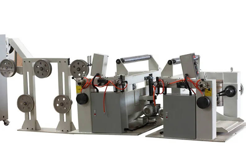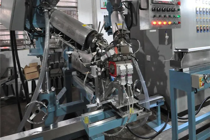
Choosing between chemical and physical foaming extrusion comes down to the cable you are producing and the dielectric tolerance you have to hit. Both methods replace solid polymer with a cellular structure to lower dielectric constant and signal loss, but they generate that cellular structure in different ways and place different demands on the extruder, the screw geometry, and the downstream cooling path. This guide compares the two methods on cell structure, dielectric consistency, equipment, yield, cost, and cable-family fit, then walks through process control points that decide the running yield.
What Foamed Insulation Does in a Cable
Foamed insulation is polymer with a controlled cellular structure: a fraction of the volume is gas-filled cells instead of solid material. Replacing solid polymer with gas lowers the effective dielectric constant of the insulation, which reduces signal loss at high frequency, and it cuts the insulation’s weight per metre. The two practical metrics buyers track are dielectric constant stability along the cable length and capacitance stability, both of which depend on how uniform the cell structure is from one metre of cable to the next.
For data, telecom, and coaxial cable families, the cellular structure is essential rather than optional, because solid polymer would deliver too much loss at the frequencies the cable is expected to carry. For commodity low-voltage and power cables, foaming is rarely used because solid polymer already meets the electrical requirements. The decision between chemical and physical foaming only matters when the product calls for foamed insulation in the first place, and both methods run on a properly configured extrusion line.
How Chemical Foaming Extrusion Works
Chemical foaming uses a foaming agent — typically a chemical blowing agent blended into the polymer as a masterbatch or dosed at the hopper — that decomposes at a defined temperature inside the extruder and releases gas. The gas dissolves in the molten polymer and forms cells as the melt exits the crosshead and the pressure drops. The result is a foamed structure whose cell size and uniformity depend on the decomposition kinetics of the blowing agent, the melt temperature, the residence time, and the cooling profile.
Equipment-side implications of chemical foaming are:
- Foaming-agent decomposition temperature must be matched to the polymer melt window. Too low and the gas escapes before cells form; too high and the cells collapse or coarsen.
- The screw and barrel geometry must avoid excessive shear at the dosing zone, which can trigger premature decomposition.
- Cooling profile is critical. Uneven cooling produces uneven cell sizes and dielectric drift along the run.
Because the gas is generated inside the melt itself, the line does not need a gas injection system, which simplifies the screw path and the control system. The trade-off is that cell-size distribution is harder to keep tight, especially at the line speeds demanded by modern high-frequency cable.
How Physical Foaming Extrusion Works
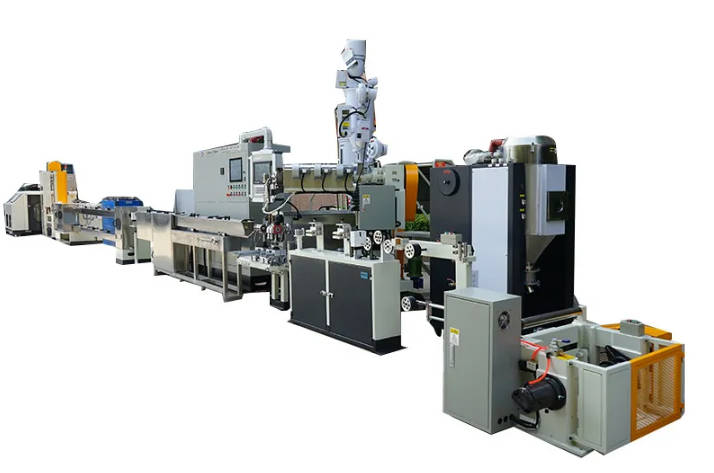
Physical foaming injects an inert gas — typically nitrogen or CO₂ — directly into the molten polymer at high pressure, downstream of the main metering zone of the screw. The gas dissolves in the melt under pressure, then expands into a fine, uniform cellular structure as the melt exits the crosshead and pressure drops. Because the gas comes from outside the polymer rather than from a chemical reaction, the cell structure can be made finer and more uniform than chemical foaming typically achieves.
This uniformity is the reason physical foaming has become the default for high-frequency data cable, twinax, and coaxial products. Tighter cell structure means tighter dielectric constant along the run, which means tighter impedance and capacitance control, which matters when the cable is carrying multi-gigabit signals.
Equipment-side implications of physical foaming are:
- Gas injection system on the extruder (gas dosing, pressure control, mixer section) — this is what differentiates a physical-foaming line from a chemical-foaming line at the equipment level.
- More sensitive melt-temperature and pressure windows: small deviations show up as cell-size drift before they show up as diameter drift.
- For high-frequency cable, the line is usually configured for the line speeds required by the data-cable product mix; this is one of the use cases where high-speed cable machine platforms become relevant, because cell uniformity has to hold at line speed.
Chemical vs Physical Foaming: Side-by-Side Comparison
The table below summarises where each method typically wins. Treat the qualitative differences as planning guides, then confirm exact values with your cable design and the supplier’s reference recipes.
| Dimension | Chemical foaming | Physical foaming |
|---|---|---|
| Cell structure | Larger cells, broader distribution | Finer cells, narrower distribution |
| Dielectric consistency | Moderate; depends on agent and cooling | High; gas pressure and melt uniformity drive cell size |
| Equipment complexity | Standard extruder; no gas injection | Extruder with gas injection system, pressure control, mixer section |
| Typical yield drivers | Agent selection, melt temperature window, cooling profile | Gas pressure stability, melt temperature, crosshead pressure drop |
| Capital and operating cost | Lower equipment cost; agent cost is recurring | Higher equipment cost; gas supply is recurring |
| Cable-family fit | Low-voltage and lower-frequency products | High-frequency data, twinax, coaxial, communication cable |
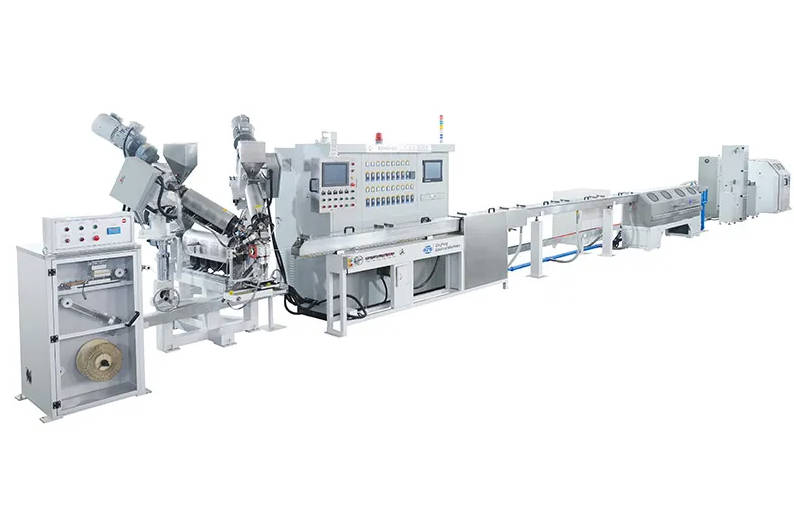
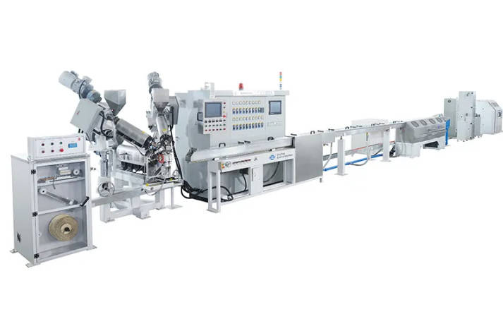
For a complete foaming extrusion line laid out end to end, including the downstream cooling, spark test, and capacitance measurement stations, the configuration changes between methods more in the extruder and gas-handling subsystems than in the rest of the line.
Which Method Suits Your Cable
Translating the comparison into a selection depends on the cable family you produce:
High-frequency data cable (Cat6A, Cat7, Cat8 and above)
Physical foaming is the standard choice. The dielectric tolerance required at multi-gigabit frequencies makes the cell-size uniformity of physical foaming a practical requirement, not a nice-to-have.
Coaxial cable, twinax / DAC, RF cable
Physical foaming is the default. Impedance and capacitance stability along the run depend on the cellular structure being fine and consistent, which is the profile physical foaming delivers.
Low-voltage general-purpose cable, control cable
Chemical foaming is often adequate and is lower in equipment cost. If the electrical requirement is met by moderate cell uniformity, chemical foaming avoids the gas-injection investment.
Power cable
Foaming is rarely used; solid polymer insulation is the standard. If your product mix is power cable, you probably do not need either foaming method.
The right method depends on the cable family you actually run, not on a generic “best practice.” Once the method is locked, cable machinery solutions and after-sales service from an experienced equipment maker help validate the reference recipes against your specific line and product mix. For broader context on how these cables connect to the wider wire-and-cable product mix, see the overview of cable making machine applications across telecom, power, and new-energy lines.
Process Control Points That Decide Yield
Method selection alone does not determine yield. Five control points typically decide whether the line runs cleanly or whether cell-size drift and capacitance drift start showing up in QC:
- Melt temperature window: foaming polymers have a narrower working range than solid polymers. A drift of even a few degrees can change cell size.
- Gas pressure stability (physical foaming): injection pressure directly drives cell size; fluctuation shows up as dielectric drift.
- Crosshead and die temperature profile: temperature uniformity at the die affects cell nucleation and growth.
- Cooling trough setup: water temperature, immersion length, and line speed determine whether cells freeze at the right size or keep coarsening.
- In-line diameter and capacitance measurement: catches drift before it becomes scrap. The capacitance reading is often the first signal that cell uniformity has moved.
Specifying these stations up front in the RFQ is cheaper than retrofitting them on a built line. Specify the sensor models, the control loops, and the data logging interface in the same document as the extruder and screw selection.
FAQ
Is physical foaming always better than chemical foaming?
No. Physical foaming delivers finer cells and tighter dielectric consistency, which matters for high-frequency data and coaxial cable. For lower-frequency products where moderate cell uniformity is acceptable, chemical foaming is a reasonable and lower-cost choice. The right answer depends on the cable family and the dielectric tolerance you have to hit.
Can one extrusion line run both chemical and physical foaming?
Usually not directly. Physical foaming requires a gas injection system, pressure control, and a mixer section that chemical foaming lines typically do not have. Some manufacturers design hybrid lines that can switch, but most production lines are configured for one method and stick to it.
Which insulation materials can be foamed?
Common foamed insulation materials include PE (polyethylene), PP (polypropylene), and FEP (fluorinated ethylene propylene, used for high-temperature and high-frequency applications). The choice depends on the cable family’s electrical, thermal, and regulatory requirements, and it constrains which foaming method is workable on your line.
How does foaming affect capacitance control?
Foaming lowers the effective dielectric constant of the insulation, which is one of the reasons it is used. The trade-off is that any drift in cell size along the run shows up as capacitance drift. Physical foaming’s tighter cell uniformity translates directly into tighter capacitance control, which is why it dominates high-frequency cable production.
Conclusion
The right foaming method depends on the cable family and the dielectric tolerance the product has to hit. Chemical foaming is the lower-cost choice where moderate cell uniformity is acceptable. Physical foaming is the standard for high-frequency data, twinax, coaxial, and communication cable because cell uniformity and capacitance control depend on it. Method selection drives the extruder configuration and the gas-handling subsystems, while process control — melt window, crosshead temperature, cooling profile, in-line capacitance measurement — drives the running yield. Specifying sensors, recipes, and the data-logging interface in the RFQ is cheaper than retrofitting them later.
For a method-and-line configuration review, share the target cable family, the dielectric or capacitance tolerance you need to hold, the current extruder configuration, and the standard the cable has to meet. With those inputs, an experienced equipment maker can recommend the foaming method and the line configuration that fit your product mix.