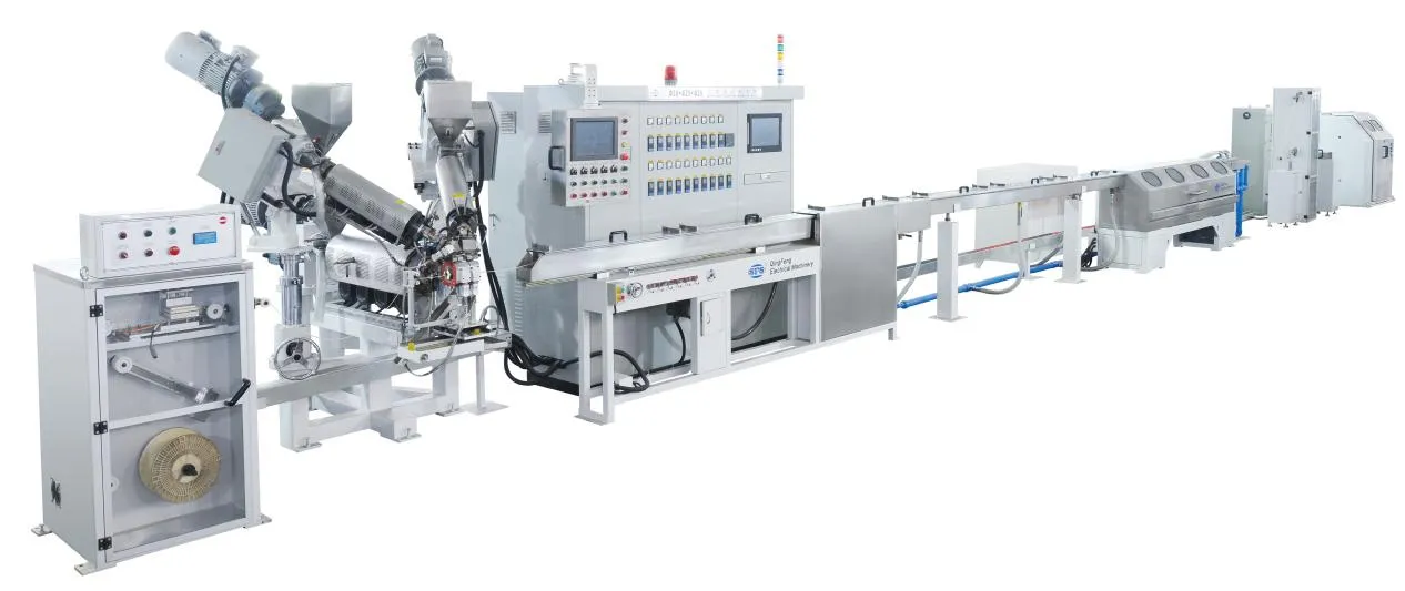
Planning an efficient extrusion line layout requires balancing machine dimensions, utility hookups, and operator clearance before equipment arrives on the plant floor. A standard extrusion line operates as an interconnected linear system: raw plastic enters through an extruder barrel, passes through specialized tooling, cools inside vacuum or spray calibration tanks, and feeds into downstream pullers, cutters, or winders.
Underestimating equipment footprint, service accessibility, or supply capacities leads to costly retrofit trenching and avoidable installation cost, thermal hazards, and unplanned operational downtime.
This guide breaks down linear space calculations, utility supply sizing (power, closed-loop water, and compressed air), maintenance clearances, and compliance boundaries necessary to plan a functional manufacturing floor — and to confirm, before signing, that a given line can actually fit the factory you already have.
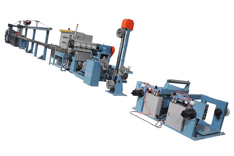
Linear Space Calculation: From Extruder to Downstream Equipment
Determining total floor footprint begins by mapping the processing distance required for continuous production. An extrusion line cannot simply be measured by summing the physical frame lengths of individual machines; cooling residence time dictates line length. High-output polymers or thick-walled profiles require extended immersion cooling or vacuum sizing lengths to set their geometry without internal structural stress or ovality.
In-Line vs. L-Shaped Configurations: Spatial Pros and Cons
Facilities generally adopt one of two primary architectural layouts:
- In-Line Layout (Straight Line): The extruder, die head, calibration baths, caterpillar haul-off, and cutoff unit are placed in an unbroken linear axis. This arrangement provides an uninterrupted material path, simplifying optical alignment, center-line laser calibration, and raw-material-to-packaging workflow. It requires a building bay with substantial continuous length.
- L-Shaped or U-Shaped Configurations: Directional guide rolls, haul-off angles, or intermediate cooling bends re-route semi-rigid extrudates (such as specific flexible tubings, filaments, or coated wires). This setup splits overall length across orthogonal bays, fitting within wider, shorter facilities. However, it introduces mechanical turning friction and potential bend-radius tension that must be synchronized with precision drive motors.
| Configuration | Floor Geometry | Material Compatibility | Material Flow & Logistics | Foundation & Alignment |
|---|---|---|---|---|
| In-Line Configuration | Narrow, long linear bay | Universal (rigid pipe, profiles, sheets, flexible tubes) | Direct entry to finished goods staging | Single-axis leveling; straightforward laser alignment |
| L-Shaped / U-Shaped | Square or broad workshop bays | Flexible materials, small-diameter filaments, wire coating | Compact grouping of operator stations | Multi-axis synchronization; requires precise transfer guidance |
Height Clearances for Hoppers, Feeders, and Overhead Cranes
Vertical space planning is frequently overlooked until overhead obstructions interfere with material handling:
- Feeding Stations and Mezzanines: Gravimetric blenders, vacuum loaders, and multi-component dosing hoppers mounted above the extruder throat substantially increase the vertical envelope. Allow dedicated vertical space for loading wand clearance and daily hopper cleaning.
- Overhead Bridge Cranes: Die maintenance and barrel replacement frequently demand overhead lifting. Plan clearance between the highest equipment point and the bottom chord of building trusses or crane hooks to prevent lifting interference during heavy changeovers.
Where floor length is the binding constraint, a vertical rather than horizontal line orientation trades bay length for tower height — a decision that must be made against the real building envelope, not after rigging begins.
Maintenance Clearances: Sizing for Tooling, Screw Pulling, and Servicing
Operational clearance must accommodate both routine production and major mechanical maintenance. Sizing a layout strictly around machine envelopes leads to severe maintenance bottlenecks when components require repair or changeover — the same access constraints that dominate an extrusion line maintenance checklist once the line is running.
Screw and Barrel Removal Clearance
Extracting an extruder screw is the most demanding spatial task on the line. The layout must provide an unobstructed linear path aligned directly with the barrel axis:
Minimum front pull clearance = Screw length + Tooling overhang + Handling safety margin
- Front Pull vs. Rear Pull: Most standard single-screw extruders require pulling the screw forward through the barrel after dismounting the adapter and die head. If the downstream cooling tank is fixed in place without caster tracks or lateral slide rails, the entire tank must be disconnected from utilities and relocated to extract the screw.
- Clearance Buffers: Maintain at least 1.5 to 2.0 meters of open linear corridor beyond the screw’s total length to allow maintenance technicians, mobile gantry cranes, and support cradles to maneuver without striking adjacent production machinery.
Screw length itself is not a fixed number — it follows from the custom screw and barrel configuration specified for the polymer and output target, so lock the screw design before you finalize the pull corridor.
Die Head Disassembly and Downstream Servicing Zones
Die heads operate at high temperatures and require regular disassembly, cleaning, and recalibration.
- Die Carts and Swing Gates: Heavy extrusion dies require counterbalanced swing hinges or heavy-duty rolling service carts. Ensure the floor adjacent to the adapter clamp remains clear of electrical pedestals or pneumatic drops to let carts park flush against the barrel.
- Control Panel Swing Radius: Industrial electrical enclosures require a minimum front clearance (often regulated at 0.9 to 1.2 meters depending on local electrical safety codes) with uninterrupted 90-to-110-degree door swing for internal diagnostics.
Utility Infrastructure Planning: Power, Water, and Pneumatic Supply
Well-engineered utilities prevent voltage drops, localized floor flooding, and pressure fluctuations that destabilize melt temperature and haul-off speeds. To ensure long-term operational efficiency, engineering teams often evaluate complete extrusion line solutions that unify upstream processing with matched utility drops.
| Utility Stream | Infrastructure Source | Target Line Equipment | Delivery & Interface Medium | Secondary / Discharge Return | Engineering Consideration |
|---|---|---|---|---|---|
| Electrical Power | Overhead Busway / Gantry | Extruder Drives & Control Panels | High-amperage armored cable drop | Grounding busbar grid | Isolate drive cables from instrumentation to prevent VFD harmonic noise |
| Process Cooling Water | Central Chiller & Cooling Tower | Vacuum Sizing & Cooling Baths | Insulated rigid piping manifolds | Sloped sub-floor drainage trench | Stable supply pressure is critical to prevent dimensional variation |
| Compressed Air | Plant Air Compressor Station | Haul-Off Clamps & Cutoff Units | Filtered pneumatic flex-drop lines | Atmospheric silencer exhausts | Requires refrigerated drying to eliminate moisture in pneumatic valves |
Electrical Drops and Cable Trench Routing
Extrusion lines concentrate substantial electrical loads across drive motors, barrel heating zones, and downstream synchronization servos — the same three loads that energy-saving drives and heating systems are designed to trim:
- Overhead Drops vs. Sub-Floor Trenches: Overhead busway drops prevent cable damage from forklift traffic and keep floor areas clear for washing. Where high-amperage cables connect the main distribution board to extruder drives, sealed floor trenches with flush steel covers prevent tripping hazards while shielding signal wiring from drive noise.
- Harmonic Isolation: Variable frequency drives (VFDs) powering extruders and pullers should have control cables routed in segregated conduits away from three-phase heater leads to prevent signal interference that can disrupt sensitive melt pressure transducers and temperature sensors.
Closed-Loop Cooling Water and Chiller Integration
Calibrating molten plastic requires substantial, controlled heat removal. Inadequate water circulation causes surface defects, uneven shrinkage, and internal stress in profiles and pipes:
- Flow and Pressure Consistency: Vacuum calibration tanks and cooling baths require balanced inlet pressure. Fluctuations in supply pressure directly alter the water level and cooling rate, leading to dimensional variances in the finished product — the same mechanism behind concentricity and wall thickness deviation on cable lines.
- Closed-Loop Recirculation: Industrial lines rely on closed-loop chiller circuits paired with outdoor evaporative cooling towers. Using open single-pass water leads to scale buildup inside internal cooling jackets and heat exchangers, degrading heat transfer efficiency over time.
- Floor Drainage Trenches: Position high-capacity, sloped drainage trenches directly beneath sizing tanks to capture water carryover and overflow during purge cycles, cleaning, or sizing sleeve adjustments.
Compressed Air Delivery and Filtration Requirements
Downstream machinery — including pneumatic haul-off clamping belts, flying cutters, dump tables, and coil strapping arms — depends on continuous clean air:
- Air Preparation: The pneumatic supply must be passed through dedicated refrigerated dryers and multi-stage coalescing filters. Water vapor or oil carryover within factory lines causes solenoid valve stick-slip, degrading cutter synchronization and leading to cut-length variances.
- Pressure Accumulators: Position local air receiver tanks near rapid-actuation units (such as pneumatic guillotine cutters) to prevent pressure sags along the main header during rapid cycling.
Material Flow and Logistics Pathways Around the Extrusion Line
A high-volume extrusion line processes substantial quantities of resin pellets and creates substantial scrap for recycling. Isolating material transport routes from the main operational line prevents warehouse bottlenecks.
| Process Stage | Origin / Staging Point | Transport & Transfer Mode | Destination Equipment | Waste / Byproduct Stream | Recovery & Handling Action |
|---|---|---|---|---|---|
| 1. Resin Delivery | Raw Material Storage / Silos | Vacuum Loader Conveying Pipe | Extruder Throat & Dosing Hopper | None (Enclosed Transfer) | Continuous level sensor feedback to vacuum pump |
| 2. Primary Extrusion | Extruder Hopper & Barrel | Single/Twin Screw Melt Pumping | Tooling & Extrusion Line | Start-up Purge Residue | Manual purge collection into heavy-duty quench drums |
| 3. Downstream Processing | Vacuum Calibration & Cooling Tanks | Caterpillar Haul-Off Drive | High-Speed Flying Cutoff / Winder | Calibration start-up waste & edge trim | Immediate routing to scrap staging carts |
| 4. In-Line Scrap Recovery | Cutoff / Winder Trimming Unit | Manual or Automatic Conveyor | Granulator & Grinding Station | Dust & Sized Flakes | Soundproof acoustic enclosure dampens grinding noise |
| 5. Regrind Recirculation | Granulator Discharge Port | Pneumatic Venturi Return Line | Gravimetric Proportional Blender | Re-incorporated material stream | Blended precisely with virgin resin at controlled ratios |
Raw Material Feeding and Bulk Storage Positioning
- Pellet Delivery Corridors: Whether handling 25-kg bags on pallets, bulk big-bags (FIBCs), or centralized pneumatic silo pipes, maintain dedicated aisles for transport. Primary transit lanes must provide adequate width (typically 2.5 to 3.0 meters) for counterbalanced forklifts or automated guided vehicles (AGVs) to pass without entering operator control zones.
- Drying and Blending Layout: Locate dehumidifying dryers and gravimetric batch blenders as close to the extruder throat as vertical clearances permit to shorten pneumatic delivery runs and prevent ambient moisture regain in hygroscopic engineering polymers.
Finished Profile/Pipe Egress and Scrap Regrind Return
- Linear Egress Corridors: Finished products exiting cutters or coilers require clear directional routing to packing areas. Long, rigid pipe or profile sections require unobstructed runout tables and lateral transfer racks to prevent structural bending before final bundling.
- Offline Granulation: Position granulators for start-up lumps and scrap offcuts outside immediate operator workstations to mitigate ambient noise and airborne dust. Provide an organized path to return regrind back into blending stations.
Safety Clearances, Thermal Zones, and EHS Compliance
Occupational safety regulations (including OSHA and EN/ISO machinery standards) define physical space requirements around continuous processing machinery. When engineering floor layouts, facilities must factor in machinery designs like custom extrusion lines that accommodate integrated perimeter fencing, access interlocks, and emergency trip devices — and must budget time for operator safety and emergency-response training, since clearances only work if people respect them.
| Plant Zone | Primary Hazard | Regulatory / Layout Requirement | Required Clearance Distance | Engineering Control Measure |
|---|---|---|---|---|
| Perimeter Walkway | Forklift traffic & material transit | Unobstructed emergency pedestrian egress | ≥1.0 m to 1.2 m continuous path | Yellow demarcation stripes; zero floor obstructions |
| Extruder Barrel Area | Thermal burn hazards (180°C – 300°C+) | Ventilation & barrier clearance | ≥1.0 m service perimeter | Perforated sheet guards & high-efficiency insulation blankets |
| Downstream Haul-off & Cutters | High-torque pinch points & rotating blades | Interlocked physical safety enclosures | Full enclosure perimeter around moving tooling | Emergency cable trip-wires along full haul-off length |
| Electrical Control Cabinets | High-voltage arc & maintenance access | Front panel door swing clearance | ≥0.9 m to 1.2 m unobstructed frontal arc | 90° – 110° swing radius clear of piping pedestals |
Emergency Egress Corridors and Operator Walkways
- Clear Walkway Widths: Maintain primary personnel walkways of at least 1.0 to 1.2 meters around the line perimeter. Keep this space free of ground-level hoses, temporary purge bins, or electrical drops.
- Emergency Egress: Personnel must never be boxed in between a hot extruder barrel and a building wall. Ensure clear access pathways to exits and install unbroken emergency trip wires along the entire downstream haul-off path where pinch-point hazards exist.
Guarding High-Temperature Barrels and Moving Haul-Off Systems
- Thermal Protection: Extruder barrel heating zones often operate between 180°C and 300°C (or higher for engineering resins). Install ventilated metal safety shrouds and insulation blankets around the barrel to prevent accidental operator contact while ensuring smooth airflow for cooling blowers.
- Pinch Point Enclosures: Caterpillar pullers and rotary cutters possess continuous pinch points. Guarding must incorporate interlocked safety switches that instantly cut power to drive motors if access doors are opened during continuous operation.
Pre-Installation Engineering Checklist for Plant Managers
Before scheduling equipment rigging and positioning, the facility engineering team should verify that all structural and service parameters meet project requirements — and confirm with the supplier’s installation and commissioning support team which items they will cover versus which remain the plant’s responsibility.
| Category | Verification Item | Engineering Acceptance Standard | Sign-Off Status |
|---|---|---|---|
| Civil & Foundation | Floor Slab Thickness | Minimum 150–200 mm reinforced concrete, crack-free | [ ] Verified |
| Floor Levelness | Tolerance within ±2 mm per 3 m span for straight-line tracking | [ ] Verified | |
| Drainage Trenching | Grated, sloped trench directly beneath tank drainage outlets | [ ] Verified | |
| Clearances | Screw Pull Linear Path | Direct axis clearance equal to screw length plus 1.5–2.0 m | [ ] Verified |
| Main Access Walkways | Unobstructed width of at least 1.0 m along all maintenance panels | [ ] Verified | |
| Ceiling / Crane Hook | Minimum 1.5 m lift hook clearance above the highest hopper point | [ ] Verified | |
| Electrical | Supply Voltage & Drops | Verified supply capacity matching total connected motor/heating kW | [ ] Verified |
| Grounding & Earth | Dedicated plant ground with resistance conforming to local codes | [ ] Verified | |
| Water & Cooling | Chilled Loop Flow Rate | Flow and pressure matching maximum heat dissipation requirements | [ ] Verified |
| Supply Pressure Stability | Regulated inlet pressure with minimal fluctuations | [ ] Verified | |
| Pneumatics | Air Quality & Dryness | Oil-free, dry air supply, regulated to line operating requirements | [ ] Verified |
Aligning Machine Dimensions with Factory Floor Layouts
Every extrusion line layout balances equipment dimensions, processing requirements, and physical plant limitations. Planning linear space, maintenance clearances, utility infrastructure, and safety corridors in advance eliminates the need for expensive structural retrofits during commissioning.
When configuring new production workshops or adapting existing plant floors for higher capacity, consulting machine manufacturers early ensures that footprint dimensions and utility hookup points are tailored to your physical building infrastructure. Where the bay cannot be extended, compare adding a second line against buying one higher-output line before committing floor space.
For projects requiring specialized tooling paths, space-saving layouts, or specific downstream arrangements, developing a cohesive layout plan around turnkey plastic extrusion line systems helps maintain project timelines, operational safety, and continuous production efficiency.
These installation and alignment videos illustrate how industrial facilities rig, align, and organize complete extrusion machinery across shop floor bays.
Key Takeaways
- Cooling Distance Dictates Footprint: Total line length depends heavily on cooling residence time; thicker walls and high-output runs require longer water and vacuum sizing paths.
- Account for Screw Extraction Early: Sizing a layout solely around the machine envelope leads to operational issues; maintain an unobstructed linear space in front of the barrel equal to the screw length plus a 1.5 to 2.0-meter handling margin.
- Segregate Utility Drops and Drives: Isolate variable frequency drive control wiring from high-amperage heater power feeds to prevent electrical noise, and supply dry, regulated compressed air to avoid cutter synchronization errors.
- Establish Clear Material and Egress Corridors: Isolate forklift resin delivery corridors from primary operator access points, and install uninterrupted 1.0-meter walkways to meet emergency egress standards.
Frequently Asked Questions (FAQ)
How much total floor space is typically required for a plastic extrusion line?
Total floor space depends on the application, output capacity, and product rigidity. Small-diameter filament or tubing lines may require a linear footprint of 10 to 15 meters, whereas high-capacity rigid PVC pipe, profile, or sheet extrusion lines often require 30 to 60 meters of linear length. In addition to machine length, factor in at least 1.5 meters of open width on each side for operator safety and a clear pull corridor ahead of the extruder barrel.
How do I calculate the linear clearance needed for extruder screw removal?
To calculate screw removal clearance, take the total physical length of the screw, add the length of the adapter and die head, and add a safety buffer of 1.5 to 2.0 meters. This ensures maintenance personnel have adequate space to install extraction tooling, attach rigging slings, and maneuver mobile crane dollies without hitting walls or adjacent machinery.
Why does cooling tank length affect the overall factory layout so significantly?
Thermoplastics retain significant internal heat when exiting the die. The extrudate must remain in temperature-controlled water baths until its core cools below its heat deflection temperature; exiting prematurely leads to warping, ovality, and dimensional instability. Higher production speeds require longer cooling paths to ensure adequate residence time, directly extending the required physical length of the factory bay.
What are the main hazards of inadequate utility sizing in an extrusion plant?
Undersized or fluctuating cooling water supplies cause inconsistent wall thickness, internal stresses, and surface defects. Fluctuating compressed air lines lead to erratic haul-off clamping pressures and irregular cut lengths. Unshielded or overloaded electrical lines can cause harmonic interference in sensitive drive controllers, resulting in unstable screw speeds and melt pressure fluctuations.
Planning a new bay or re-laying an existing floor? Send us your building dimensions, utility capacity, and target output and we will map a line configuration that fits the space you actually have.